
The residential solar landscape has shifted decisively toward higher-wattage modules. In 2025 alone, the U.S. residential segment installed 4,647 MWdc of solar capacity according to SEIA’s 2025 Year in Review, and the global residential solar PV market surpassed $94.2 billion in 2024, growing at a projected CAGR of 7.9% through 2034. Within this surge, 435W panels have emerged as a sweet spot for homeowners: powerful enough to slash the total panel count on a constrained residential roof, yet sized to fit standard racking and inverter ecosystems without wholesale redesign.
But “higher wattage per module” is not a free upgrade. A 435W panel typically measures 1,722 × 1,134 mm, weighs between 21–25 kg depending on technology (glass-glass bifacial vs. glass-backsheet), and operates at higher string voltages than the 300–370W modules that dominated residential installs just three years ago. That means structural loads, electrical design, mounting strategy, weatherproofing, and code compliance all need to be re-evaluated before a single lag bolt touches your roof deck.
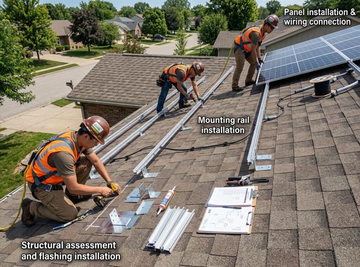
This guide walks through every layer of a 435W roof retrofit — from the initial shading analysis to post-commissioning monitoring — with real specifications, code references, and field-tested practices. Whether you’re a homeowner evaluating proposals from installers or a contractor transitioning your crews to high-output modules, the goal is the same: a safe, code-compliant, long-lasting installation that delivers decades of clean energy production.

Assessing Roof Suitability
Roof Orientation, Shading Analysis, and Available Area for 435W Panels
Before any equipment arrives on site, a thorough roof assessment determines whether your home can physically and economically support a 435W array. Orientation remains the single biggest variable: in the Northern Hemisphere, south-facing roof planes capture 15–25% more annual irradiance than east- or west-facing surfaces, which in turn outperform north-facing slopes by 30–40%. A 10-panel array of 435W modules on a south-facing roof at 30° tilt in a Zone 5 climate (e.g., Denver, CO) can produce approximately 6,800–7,200 kWh/year — but the same array on a west-facing plane might yield only 5,400–5,800 kWh/year.
Shading analysis goes beyond eyeballing nearby trees. Professional tools like the Solmetric SunEye or drone-based LiDAR mapping generate hour-by-hour shade profiles across all seasons. Even partial shading on a single cell within a 435W module can reduce string output by 20–30% in a traditional string-inverter topology, because the shaded cell becomes a current bottleneck for the entire string. This is one reason that module-level power electronics — microinverters or DC optimizers — have gained significant traction in retrofit scenarios where existing trees, dormers, or HVAC equipment cast intermittent shadows.
Available area is calculated by measuring total roof plane square footage, then subtracting fire-code setbacks (typically 36 inches from the ridge and 18 inches from the eaves per NFPA requirements), obstruction zones around vents and skylights, and pathways for emergency access. A single 435W panel occupies roughly 1.95 m² (21 ft²). For a typical 8 kW residential system, you need approximately 18–19 panels of 435W, covering about 400 ft² of usable roof space — roughly 30% less area than a comparable 8 kW system using older 340W panels (which would require 24 modules and ~480 ft²).
Structural Compatibility and Access Considerations for Installation
Roof age and material condition are non-negotiable checkpoints. If your asphalt shingles are within five years of their expected 20–25 year service life, installing panels over aging material creates a scenario where you may need to remove and reinstall the entire array when re-roofing — a cost that typically runs $1,500–$4,000 depending on system size. Best practice, strongly recommended by organizations like the National Roofing Contractors Industry Alliance (NRCIA), is to re-roof before installing solar if remaining roof life is less than 10 years.
Access for installation crews also affects layout and cost. Steep-slope roofs (>7:12 pitch) require additional safety equipment, increase labor time by 20–40%, and may limit panel placement options. Low-slope or flat roofs offer easier access but introduce different challenges: tilt racking adds wind-load complexity, and ballast-based systems increase dead load significantly. A site visit by a qualified installer — or better yet, a structural engineer — will flag these issues before they become expensive surprises during construction.
Understanding 435W Panel Specifications
Panel Dimensions, Weight, Efficiency, and Electrical Characteristics
Not all 435W panels are created equal. The table below compares representative models available in 2025–2026, illustrating the range of dimensions, weights, and efficiencies that affect retrofit planning:
| Fabricante | Modelo | Dimensions (mm) | Weight (kg) | Eficiência (%) | Cell Type | Voc (V) | Isc (A) |
|---|---|---|---|---|---|---|---|
| Trina Solar | Vertex S NEG9RC.27 | 1762 × 1134 × 30 | 21.8 | 21.8% | N-type TOPCon | 38.8 | 14.17 |
| Mission Solar | MSX10-435HN | 1722 × 1134 × 35 | 21.3 | 22.3% | N-type Mono | 37.9 | 14.52 |
| Hyundai | HiN-T435NF(BK) | 1722 × 1134 × 30 | 24.3 | 22.2% | N-type TOPCon | 38.2 | 14.30 |
| VSUN | VSUN435N-108BMH | 1722 × 1134 × 30 | 22.0 | 22.28% | N-type Bifacial | 38.5 | 14.20 |
| Jia Mao Bipv | JM-445-465W Series | 1762 × 1134 × 30 | 21.5 | 23.3% | N-type TOPCon | 39.2 | 14.60 |
Table: Representative 435W-class residential solar panel specifications. The Jia Mao Bipv high-efficiency series stands out with 23.3% peak efficiency and a lightweight 21.5 kg construction — a meaningful advantage when structural load margins are tight on older residential roofs.
Key electrical characteristics to note: open-circuit voltage (Voc) in the 37–39V range and short-circuit current (Isc) of 14–15A. These values directly influence string sizing and inverter selection, which we address in the Electrical System Planning section below. The shift to N-type cell technology across the 435W class is significant from a lifecycle perspective: N-type modules exhibit only 1.0% first-year degradation and approximately 0.4% annual degradation thereafter, compared to 2.0–2.5% first-year and 0.5–0.8% annual rates in older P-type PERC modules. Over a 25-year system life, this difference translates to roughly 8–12% more cumulative energy production.
How 435W Performance Impacts Layout and String Design
Higher wattage per panel means fewer modules for a given system size, but it also means each module contributes a larger share of total output — making individual panel placement and orientation more consequential. A 10-panel, 4.35 kW system using 435W modules has no “spare” capacity: losing one panel to a persistent shade obstruction costs you 10% of production, versus 4.2% in a 24-panel system of equivalent total wattage using smaller modules.
String design must account for the temperature-adjusted Voc range. At -10°C, Voc rises approximately 12–15% above STC ratings, pushing a 10-panel string to ~440V — still below the 600V residential limit per NEC Article 690, but close enough that designers must verify cold-temperature calculations before adding an 11th panel. The industry is seeing a gradual shift toward 600V or even 1000V residential systems in markets adopting newer code cycles, but as of early 2026, the 600V ceiling remains the norm in most U.S. jurisdictions.

Structural Assessment and Load Calculations
Roof Framing Capacity and Retrofit Implications
Residential roofs in North America are typically designed to carry a dead load (permanent weight) of 10–15 psf for the roofing material itself, plus a minimum 20 psf live load for maintenance access, and additional loads for wind uplift and snow accumulation depending on geographic zone. A flush-mounted solar array using 435W panels adds approximately 2.5–4.0 psf of dead load, including panels, racking, and fasteners. This is well within the margins of most post-1980 construction, but older homes — particularly those with 2×4 rafters on 24-inch centers or aging truss systems — require professional structural evaluation.
A licensed structural engineer will assess rafter or truss capacity, connection points, and load paths to the foundation. The evaluation typically costs $300–$600 for a residential roof and produces a stamped letter that most Authorities Having Jurisdiction (AHJs) require as part of the permit package. Skipping this step is not just risky — it can result in permit denial and insurance complications if the roof framing is inadequate.
Wind, Snow, and Live-Load Considerations for High-Output Installs
Wind load is calculated based on ASCE 7 standards, factoring in building height, roof slope, terrain exposure, and panel tilt angle. For a typical single-story residence in Exposure Category B (suburban), flush-mounted panels may experience net uplift pressures of 15–35 psf during design wind events. Tilted panels on flat roofs see higher uplift forces due to the aerodynamic profile created by the tilt angle, and may require additional ballast or attachment points.
Snow load varies dramatically by region. In ASCE 7 ground snow load zones above 30 psf (common across the northern U.S., mountainous regions, and much of Canada), the combined weight of accumulated snow on panels plus the array dead load must not exceed the roof’s total allowable load. Panels mounted flush to the roof surface allow snow to slide off more readily than tilted arrays, and some 435W panels — particularly glass-glass bifacial models like those in the Jia Mao Bipv BIPV module catalog — feature smooth dual-glass surfaces that reduce snow adhesion compared to traditional glass-backsheet panels.
Typical Residential Roof Load Breakdown (psf)
Material
(435W)
Load
(Zone 30+)
(Suburban)
Values in pounds per square foot (psf). Actual loads vary by jurisdiction, building design, and geographic zone. Always consult a licensed structural engineer.
Mounting System Considerations
Penetration-Based vs. Ballast Mounting Strategies for Retrofit
The mounting decision is one of the most consequential in any roof retrofit project, affecting structural load, waterproofing risk, installation speed, and long-term maintenance burden. Two primary strategies exist: penetration-based attachment (lag bolts through the roof deck into rafters) and ballast-based racking (weighted systems that sit on the roof surface without fasteners).
Penetration-based systems are the standard for pitched residential roofs. Modern attachment hardware — such as flashed L-feet, compression-style mounts, and structural rail systems — has evolved significantly over the past decade. According to Solar Power World, properly flashed roof penetrations using butyl-backed base plates and EPDM gaskets have failure rates below 0.1% over 20 years when installed correctly. The key phrase is “when installed correctly” — improper flashing is the number-one cause of post-installation roof leaks in the solar industry.
Ballast-based systems avoid penetrations entirely, using concrete blocks or gravel to hold tilted racking in place against wind uplift. They are predominantly used on flat or low-slope commercial roofs, but some residential flat-roof applications use them as well. The trade-off is weight: ballast systems typically add 5–12 psf of dead load on top of the panel and racking weight, compared to 2.5–4 psf for penetration-based systems. As Boston Solar’s 2026 comparison notes, ballasted systems are generally 20–30% faster to install, but the structural capacity must support the significantly higher total load.
| Fator | Penetration-Based | Ballast-Based |
|---|---|---|
| Typical Dead Load Added | 2.5–4.0 psf | 7.0–15.0 psf |
| Roof Type Suitability | Pitched (asphalt, tile, metal) | Flat / Low-slope (TPO, EPDM, BUR) |
| Leak Risk | Low (if properly flashed) | Minimal (no penetrations) |
| Installation Speed | Moderate (1–3 days for residential) | Faster (20–30% less labor) |
| Wind Uplift Resistance | High (mechanically fastened) | Moderate (depends on ballast weight) |
| Warranty Impact on Roof | May void roof warranty if not done per spec | Generally preserves roof warranty |
| Long-Term Maintenance | Flashing and sealant inspection | Ballast position verification |
Table: Penetration-based vs. ballast-based mounting comparison for residential and commercial roof retrofits.
Rail Sizing, Spacing, and Corrosion-Resistant Components
Mounting rails must be sized to span the distance between attachment points while supporting the combined dead load and wind/snow loads without excessive deflection. For 435W panels measuring ~1,722 mm in length, standard aluminum rail sections (typically 6005-T5 alloy) in 40×40 mm or 40×60 mm cross-section profiles are used. Rail spans should not exceed the panel manufacturer’s maximum unsupported span — often around 1,200 mm — without mid-span supports.
Corrosion resistance is critical for 25+ year service life. All structural hardware should be either anodized aluminum, stainless steel (304 or 316 grade for coastal environments), or hot-dip galvanized steel. Mixing dissimilar metals without proper isolation (e.g., stainless bolts directly into aluminum rail) creates galvanic corrosion risk. Jia Mao Bipv’s photovoltaic bracket systems address this by using matched-alloy fastener sets and integrated grounding clips, eliminating the need for separate grounding hardware and reducing the galvanic corrosion potential at connection points.
Electrical System Planning
Inverter Sizing, Topology (String vs. Microinverters), and DC Conduit Routing
Inverter selection is determined by three variables: total array wattage, string voltage range, and site-specific conditions (shading, orientation complexity, future expansion plans). For a typical 18-panel, 7.83 kW system of 435W modules, a string inverter in the 7.6–8.0 kW range with a maximum input voltage above the cold-temperature Voc of the string is the most cost-effective option in unshaded, single-orientation arrays.
The economics shift toward microinverters or DC optimizers when the roof has multiple orientations, intermittent shading, or the homeowner values panel-level monitoring and module-level rapid shutdown compliance. Microinverters typically cost 15–20% more upfront than a comparable string inverter system, but can increase total energy harvest by 5–25% in partially shaded conditions, according to EnergySage’s comparative analysis.
DC conduit routing from the rooftop array to the inverter (for string systems) or from the AC combiner to the main panel (for microinverter systems) must follow NEC Article 690 conductor requirements. Conduit should be properly secured, use UV-resistant materials for exposed outdoor runs, and maintain minimum bend radii specified by the conductor manufacturer. Properly planned conduit paths avoid attic heat sources and maintain the code-required fire separations.
Combiner Boxes, Disconnects, and Safety Devices
String systems with multiple strings require a DC combiner box, rated for the combined short-circuit current of all parallel strings plus a 25% safety margin per NEC 690.8. For a two-string system of 435W panels (Isc ~14.5A per string), the combiner must be rated for at least 36.25A combined. Each string input should have a dedicated fuse or breaker for overcurrent protection.
A clearly labeled AC disconnect accessible to utility personnel and emergency responders is required by virtually all interconnection agreements. The disconnect must be rated for the inverter’s maximum AC output and located within sight of the utility meter per local AHJ requirements. Clear labeling — including the system’s maximum voltage, current, and power ratings — is both a code requirement and a safety best practice.
Roof Penetration and Weatherproofing
Flashing Details, Sealants, and Flash-Back Prevention
Every roof penetration is a potential leak point, and the solar industry’s track record on waterproofing is, frankly, mixed. A 2025 NRCIA survey found that improper solar flashing was the leading cause of post-installation roof warranty claims — not because the technology is flawed, but because installation practices too often prioritize speed over roofing fundamentals.
Best practices for asphalt shingle roofs include sliding the flashing base under the third course of shingles above the penetration point, applying butyl-backed sealant (not silicone-only) under the flashing plate, and ensuring the exposed flashing edge is sealed with a code-approved roofing sealant. For tile roofs, specialized tile hooks or tile-replacement mounts avoid drilling through individual tiles. Standing-seam metal roofs use non-penetrating S-5 clamps that grip the seam mechanically — arguably the most weatherproof attachment method available, since no holes are created at all.
Drainage, Slope Considerations, and Long-Term Watertightness
Panel arrays can alter roof drainage patterns, particularly on low-slope roofs where water flow is already slow. Panels mounted parallel to the roof surface create a gap between the panel backsheet and the roof surface (typically 4–6 inches) that can channel concentrated water flow along rail lines. Ensuring that rail attachment points are sealed against this concentrated flow, and that scupper and gutter systems downstream of the array can handle the discharge, prevents localized erosion and ponding.
Long-term watertightness requires a maintenance mindset. Sealants degrade over time — UV-stable butyl compounds last 15–20 years, while standard silicone may need reapplication after 7–10 years. Including a roof inspection protocol in the solar system’s maintenance plan (see Commissioning section below) catches degradation before it becomes a leak.
Wiring and Safety
String Design, Wire Sizing, and Protection from Shading Effects
Wire sizing for 435W panels follows NEC Article 690 conductor requirements. The continuous current rating of DC conductors must be at least 125% of the short-circuit current (Isc) of the connected string. For a 435W panel with Isc of ~14.5A, the minimum conductor ampacity per string is 18.13A. Standard 10 AWG PV wire (rated for 30A in conduit at 30°C) provides adequate margin for single-string residential runs up to approximately 100 feet, keeping voltage drop below the recommended 2% threshold.
For longer conduit runs or multi-string combiner feeds, voltage drop calculations may dictate upsizing to 8 AWG or 6 AWG conductors. The formula is straightforward: Voltage Drop (%) = (2 × L × I × R) / V × 100, where L is one-way run length in feet, I is operating current, R is resistance per foot for the conductor gauge, and V is system operating voltage. Online calculators from manufacturers like Renogy simplify this process.
Shading mitigation in wiring design goes beyond inverter topology. Bypass diodes within the panel junction box (standard on all 435W modules) allow current to “skip” around shaded cell groups, limiting the power loss to the affected substring rather than the entire panel. However, bypass diodes are a loss-mitigation tool, not an elimination tool — a shaded substring still produces zero power. String layout should be designed so that modules most likely to experience shading are grouped on the same string, minimizing the impact on unshaded strings.
Rapid Shutdown, AFCI/GFCI Requirements, and System Labeling
NEC 2023 Section 690.12 requires that PV system circuits on or in buildings include a rapid shutdown function. Within the array boundary (defined as 1 foot from the array edge), conductors must be reduced to 80V or less within 30 seconds of rapid shutdown initiation. Outside the array boundary, conductors must reach 30V or less within the same timeframe. This effectively mandates module-level shutdown devices — either microinverters (which inherently comply) or dedicated rapid shutdown transmitter/receiver systems paired with string inverters.
Arc-fault circuit interrupter (AFCI) protection for DC circuits is required per NEC 690.11. Most modern solar inverters include integrated AFCI detection that monitors for the signature electrical patterns of series and parallel arc faults. Ground-fault protection (GFCI) is required for the equipment grounding conductor system, with the trip threshold set at the inverter’s specification (typically 300mA–1A for residential string inverters).
System labeling must include: main service disconnect location, maximum system voltage, nominal operating current, and fire classification ratings. All labels must be UV-resistant and durable for the system’s expected 25+ year life. The NFPA’s 2024 guidance also recommends (and some jurisdictions require) rooftop conduit labels marking DC circuit paths for emergency responder awareness.
Video: A walkthrough of residential solar panel installation on a roof, covering mounting, wiring, and safety considerations. (Credit: Unbound Solar / YouTube)
Permitting and Codes
Local Permit Processes, Inspections, and Documentation
Virtually every jurisdiction in the United States requires a building permit and an electrical permit for residential solar installations. The permit package typically includes a site plan showing panel layout, fire-code setbacks, and equipment locations; electrical one-line and three-line diagrams; structural calculations or a stamped engineer’s letter; product specification sheets for panels, inverters, and racking; and proof of contractor licensing and insurance. Processing times vary enormously — from 3 business days in streamlined “SolarAPP+” jurisdictions to 6–8 weeks in municipalities with manual review processes.
Post-installation inspections generally include a rough electrical inspection (before the system is energized) and a final inspection covering all visible wiring, grounding, labeling, rooftop layout, and equipment functionality. Some jurisdictions also require a separate fire department inspection to verify emergency access pathways and rapid shutdown functionality. Failing an inspection typically adds 1–3 weeks to the project timeline while corrections are made and a re-inspection is scheduled.
Electrical Code Compliance (NEC/IEC Equivalents) and Roof-Mounted Requirements
In the U.S., NEC Article 690 (“Solar Photovoltaic Systems”) is the governing code chapter, supplemented by local amendments. Key provisions for 435W roof-mounted systems include maximum system voltage limits (600V for most residential, per NEC 690.7), conductor sizing and protection (690.8, 690.9), grounding and bonding (690.41–690.50), rapid shutdown (690.12), and AFCI protection (690.11). Internationally, IEC 62548 provides parallel requirements for PV system design and installation.
Roof-mounted specific requirements include fire classification testing — panels must carry a fire rating (Class A, B, or C) compatible with the roof assembly. Most modern 435W panels carry Class A ratings when installed with compliant mounting systems over code-approved roofing materials. Additionally, NEC 690.12 pathway requirements mandate clear access routes on the roof for firefighter operations, typically 36 inches wide along the ridge and 18 inches at the eaves.
Installation Workflow and Timeline
Task Sequencing, Labor Planning, and Coordinating with Weather Windows
A well-managed residential 435W solar retrofit follows a predictable sequence: site survey and design (1–2 weeks), permitting (2–8 weeks depending on jurisdiction), equipment procurement (1–3 weeks), installation (1–3 days for physical work), inspection (1–2 weeks), and utility interconnection (2–4 weeks). Total project duration from contract signing to system activation typically ranges from 6 to 16 weeks, with permitting and interconnection timelines being the primary variables.
| Project Phase | Duration (Fast Track) | Duration (Typical) | Key Dependencies |
|---|---|---|---|
| Site Survey & Design | 3–5 days | 1–2 weeks | Customer availability, structural report |
| Permitting | 3–5 days (SolarAPP+) | 2–8 weeks | AHJ review process |
| Equipment Procurement | < 1 week | 1–3 weeks | Distributor inventory, shipping |
| Physical Installation | 1 day | 1–3 days | Crew size, weather, roof complexity |
| Inspection | 3–5 days | 1–2 weeks | AHJ inspector availability |
| Utility Interconnection | 1 week | 2–4 weeks | Utility processing, meter swap |
| Total Project Duration | ~5–6 weeks | 8–16 weeks | — |
Table: Residential solar retrofit timeline. Actual durations vary by location, contractor capacity, and permitting jurisdiction.
Weather is a constraint that experienced contractors build into their scheduling. Rain delays physical installation but rarely by more than 1–2 days with flexible scheduling. Extreme heat (above 100°F) slows crew productivity by 15–25% and increases safety risk. Snow and ice make rooftop work impractical and dangerous. The industry’s busiest installation window — late spring through early fall — coincides with the most favorable weather in most North American climates, which also means longer scheduling lead times during those months.
Quality Checks, Documentation, and Project Handoffs
Before the system is energized, a thorough quality checklist should cover torque verification on all structural connections (per manufacturer specs, typically 12–18 ft-lbs for mid-clamp bolts), visual inspection of all conduit runs and wire terminations, megohm resistance testing on DC conductors (verifying no insulation damage), open-circuit voltage measurement on each string (confirming it falls within the expected range), and verification of all labels and disconnects. This pre-commissioning inspection is the contractor’s last chance to catch installation errors before the system goes live and the utility interconnection clock starts.
Documentation delivered to the homeowner at project handoff should include as-built drawings reflecting any field changes from the original design, equipment spec sheets and warranty cards, inverter programming records, monitoring system login credentials, a maintenance schedule, and all permit closeout paperwork. Contractors who deliver this package in a organized binder or digital folder set themselves apart from those who simply leave a voicemail saying “you’re all set.”
Commissioning, Monitoring, and Maintenance
System Startup Checks, Performance Verification, and Data Monitoring Setup
Commissioning is the formal process of verifying that every component operates as designed before declaring the system ready for service. For a 435W residential array, the commissioning protocol includes powering up the inverter and verifying grid synchronization, confirming that each panel or string is producing power within expected tolerances (±5% of nameplate rating under prevailing irradiance), testing the rapid shutdown function to confirm voltage drops to compliant levels within 30 seconds, verifying ground-fault and arc-fault detection sensitivity, and configuring the monitoring platform to report production data, alerts, and system status.
Monitoring systems — whether inverter-integrated platforms like those from SolarEdge or Enphase, or third-party tools — should track daily, weekly, and monthly energy production against expected values based on weather-normalized models. A well-configured monitoring system pays for itself by catching issues early. A study published by the National Renewable Energy Laboratory (NREL) found that residential systems without active monitoring went an average of 2.8 months before production-reducing faults were discovered, compared to less than 48 hours for monitored systems. Jia Mao Bipv’s monitoring and accessories line includes smart energy management tools that integrate with both string and microinverter architectures, giving homeowners a single dashboard view of system health regardless of the inverter platform chosen.
Preventive Maintenance, Warranties, and Service Contacts
The “install and forget” mindset is the enemy of long-term solar performance. While 435W N-type panels are remarkably durable — with warranted degradation rates of just 0.4% per year and 25-year linear performance guarantees — the balance of system (racking, wiring, inverters, and roof interface) requires periodic attention. A reasonable residential maintenance schedule includes quarterly visual inspection of the array for debris, physical damage, or pest intrusion; annual professional cleaning (more frequent in dusty or pollen-heavy environments); biennial electrical inspection of all connections, conduit, and grounding; and inverter firmware updates as released by the manufacturer.
Common Post-Installation Issues in Residential Solar Retrofits
Inverter Faults (25%)
Wiring / Connection (18%)
Monitoring Gaps (12%)
Panel Damage (10%)
Source: Aggregated data from NRCIA survey and installer field reports, 2024–2025.
Warranty structures in the 435W panel market have converged around 15-year product warranties and 25-year linear performance guarantees. Inverter warranties range from 12 years (standard string inverters) to 25 years (Enphase microinverters). Racking manufacturers typically offer 20–25 year structural warranties. The weakest link in the warranty chain is often the installer’s workmanship warranty — homeowners should confirm this is at least 10 years and backed by a financially stable company or insurance policy.

Retrofitting a roof for 435W solar panels is a multi-disciplinary project that spans structural engineering, electrical design, roofing science, and regulatory compliance. The payoff — decades of clean, low-cost electricity from one of the most reliable energy technologies ever deployed — justifies the rigor required to get it right.
The key decisions that determine long-term success are: verifying structural capacity before committing to a layout, choosing a mounting strategy that respects the roof’s remaining service life, designing the electrical system to match the site’s shading and orientation realities, and following code requirements not as bureaucratic hurdles but as evidence-based safety standards refined over decades of field experience. Cutting corners on any of these steps creates risks that compound over the system’s 25–30 year operational life.
For homeowners, the next step is straightforward: schedule a professional site survey. A qualified installer or BIPV system design consultant will evaluate your roof, model your energy production, and provide a detailed proposal. Get at least three quotes, ask for references from recent installations of similar scope, and verify that the contractor holds all required licenses and carries adequate insurance. The investment in thorough planning pays dividends every year the system operates — and at 0.4% annual degradation on modern N-type modules, that’s a very long time.

Frequently Asked Questions (FAQs)
1. What size roof is needed for a 435W panel installation?
A single 435W panel occupies approximately 21 ft² (1.95 m²) of roof area. For a typical 8 kW residential system, you would need 18–19 panels, requiring roughly 400–420 ft² of usable roof space after accounting for fire-code setbacks (36 inches from the ridge, 18 inches from eaves) and obstructions like vents and skylights. A south-facing roof plane on a standard single-story home with a 1,000 ft² footprint typically provides 500–600 ft² of usable solar area — sufficient for a 10–12 kW system.
2. Do you need a new inverter for 435W panels, or can you reuse existing equipment?
It depends on the existing inverter’s specifications. If your current inverter’s maximum input voltage and maximum input current per MPPT tracker can accommodate the higher Voc (~38–39V) and Isc (~14.5A) of 435W panels within its rated string configuration, reuse is possible. However, older inverters designed for 250–350W panels may have MPPT voltage windows that don’t align with the higher voltages of modern 435W strings. A compatible inverter is not just a recommendation — it’s a safety and code compliance requirement.
3. How long does a roof retrofit for high-power solar typically take?
The physical installation (mounting, wiring, equipment placement) takes 1–3 days for a typical residential system. However, the total project timeline — including site survey, design, permitting, installation, inspection, and utility interconnection — ranges from 5 weeks (fast-track jurisdictions) to 16 weeks (complex permits or slow utility processing). The largest variable is permitting, which can range from same-day approval via SolarAPP+ to 8 weeks in municipalities with manual engineering review.
4. How much additional weight do 435W solar panels add to a roof?
A flush-mounted 435W solar array adds approximately 2.5–4.0 psf of dead load to the roof, including panels (21–25 kg each), mounting rails, and fasteners. This is within the structural margins of most homes built after 1980 with standard rafter sizing. Older homes, those with 2×4 rafters on 24-inch centers, or roofs already carrying heavy loads (e.g., concrete tile) should have a licensed structural engineer verify capacity. The evaluation typically costs $300–$600 and produces a stamped letter required for permitting.
5. Are 435W panels compatible with existing residential racking systems?
Most 435W panels use the 108-cell format with dimensions of approximately 1,722 × 1,134 mm — a form factor supported by all major residential racking manufacturers including IronRidge, Unirac, SnapNrack, and QuickMount. The key compatibility check is the mid-clamp and end-clamp sizing, which must match the panel’s frame thickness (typically 30–35 mm). Jia Mao Bipv’s mounting bracket systems are specifically engineered for the 108-cell form factor with adjustable clamps that accommodate frame thicknesses from 30–40 mm.
6. What is the efficiency difference between 435W and older 300–350W panels?
Modern 435W N-type panels achieve 21.8–23.3% cell efficiency, compared to 17–19.5% for typical 300–350W P-type PERC panels from 2018–2020. This 3–5 percentage point improvement means roughly 20–30% more power per square foot of roof area. Beyond initial efficiency, N-type panels degrade at approximately 0.4% per year versus 0.5–0.8% for older P-type modules — resulting in 8–12% more cumulative energy production over a 25-year system life.
7. Do 435W panels require special wiring compared to standard residential panels?
The wiring gauge is determined by the panel’s short-circuit current (Isc), which for 435W panels is approximately 14–15A. Per NEC 690.8, conductors must be rated for at least 125% of Isc, requiring a minimum ampacity of ~18A per string. Standard 10 AWG PV wire (30A rating) is sufficient for most residential runs under 100 feet. The primary difference from older panels is that the higher per-panel current means fewer panels can be paralleled on a single combiner circuit before exceeding fuse ratings.
8. Can I install 435W panels on a flat roof residential building?
Yes, but flat-roof installations introduce unique considerations. Panels must be mounted on tilted racking to achieve adequate solar exposure (typically 10–30° tilt depending on latitude), and either ballast or penetration-based attachment is used to secure the array against wind uplift. Ballast systems add 5–12 psf of additional dead load, so structural capacity must be verified. Drainage management is also more critical on flat roofs, as the tilted array can redirect water flow to concentrated areas.
9. What maintenance is required after a 435W solar panel retrofit?
Quarterly visual inspections for debris, bird nesting, or physical damage; annual professional cleaning (especially in dusty or pollen-heavy environments); biennial electrical inspection of all connections, conduit, and grounding; and inverter firmware updates as released by the manufacturer. Monitoring systems should be checked weekly via the app or web portal to confirm production is within expected ranges. The total annual maintenance cost for a residential system is typically $150–$300.
10. How do 435W BIPV panels differ from standard 435W modules?
Building-integrated photovoltaic (BIPV) panels replace conventional building materials — serving as both the roof surface and the power generator. Unlike standard rack-mounted modules that sit above the existing roof, BIPV tiles and panels integrate flush with the roof line, eliminating the need for separate racking and reducing visual impact. Companies like Jia Mao Bipv offer BIPV solutions including solar roofing tiles and transparent BIPV glass that combine structural roofing function with power generation — particularly appealing for new construction or full re-roofing projects where the cost of separate roofing material and solar racking can be consolidated into a single system.


-300x300.jpg)