A commercial roof that was not designed with solar integration in mind can easily add 15–25% to project cost when a PV system is retrofitted just a few years after handover. Structural reinforcement, rerouted conduit, membrane penetration re-work, and delayed utility interconnection studies are the most common culprits — and every one of them is avoidable when the right decisions are made on day one.
This guide walks EPC contractors, building developers, MEP engineers, and commercial asset managers through the full lifecycle of a solar-ready roof — from shading analysis and structural load planning through electrical design, interconnection, energy storage, and long-term O&M strategy.
Foundational Planning for Solar-Ready Design

Project Goals and Stakeholder Alignment
The most expensive mistake on a commercial solar project is not a wrong wire gauge or a miscalculated load — it is discovering at permit submission that the roof engineer, the electrical engineer, and the PV contractor have been working from three different assumptions about the system size, the equipment zone, and the conduit route. A 500 kWp rooftop system on a 30,000 m² logistics facility involves at minimum six decision-making disciplines: architecture, structural engineering, roofing/waterproofing, MEP design, solar EPC, and utility interconnection. When those disciplines are not aligned before schematic design is locked, the friction shows up in change orders rather than in design meetings.
Stakeholder alignment should happen around four concrete variables: target system capacity in kWp, acceptable roof area utilisation percentage, interconnection point and service entrance location, и target payback period or energy offset ratio. With those four numbers on the table, every other design decision — from parapet height to conduit sleeve sizing — can be evaluated against a shared goal rather than an individual discipline’s default.
Codes, Standards, and Permitting Considerations
The regulatory framework for commercial solar-ready roofs spans three overlapping code families. The 2024 International Energy Conservation Code (IECC) Appendix CB defines minimum solar-ready zone requirements — for buildings five stories or fewer, a solar-ready zone must cover at least 25% of the horizontal roof projection and must be oriented between 110° and 270° azimuth. The National Electrical Code (NEC) Article 690 governs the PV electrical system design and wiring methods. And the International Building Code (IBC) governs structural loads, fire access lanes, and equipment placement.
Permit review timelines for commercial solar in major jurisdictions typically run 4–12 weeks. Projects that pre-coordinate with the Authority Having Jurisdiction (AHJ) during design — rather than at submission — consistently see 30–40% shorter review cycles, based on data from plan review firms serving multi-state commercial portfolios. Plan sets must typically include a site plan, roof loading calculations, single-line electrical diagram, equipment specifications, and anti-islanding compliance documentation.
| Code / Standard | Scope | Key Commercial Requirement | Typical Review Body |
|---|---|---|---|
| IECC 2024 Appendix CB | Energy conservation | ≥25% roof area as solar-ready zone; conduit sleeves, load path, wiring space | Building department |
| NEC 2023 Article 690 | PV electrical systems | DC circuit protection, rapid shutdown (690.12), wiring methods, disconnects | Electrical inspector / AHJ |
| IBC 2021 | Structural / fire | Dead + live loads, wind uplift, fire access path (10-ft setbacks) | Building department |
| ASCE 7-22 | Structural loads | Wind pressure, snow load, seismic design category | Structural engineer of record |
| UL 61730 / UL 1741 | Equipment certification | Module safety, inverter anti-islanding, interconnection standards | Utility / AHJ |
| IEEE 1547-2018 | Grid interconnection | Voltage/frequency ride-through, anti-islanding, reactive power capability | Utility interconnection team |
Site, Climate, and Solar Resource Assessment

Shading Analysis Concepts and Tools
Shading is the leading cause of underperforming commercial rooftop systems — not equipment quality, not installation error. A rooftop HVAC unit that occupies 3% of roof area can shade 12–18% of the available PV zone depending on its height and orientation relative to winter sun angles. When shading affects only part of a string, the entire string’s output drops to match the weakest module, a phenomenon called the Christmas-light effect. On a 250 kWp array, that single HVAC unit shadow can cost 18,000–35,000 kWh per year in lost generation.
Professional shading analysis tools now used on commercial projects include NREL PVWatts (free, web-based, best for quick feasibility estimates), Helioscope (cloud-based, handles complex roofs and module-level modelling), PVSyst (industry standard for bankable yield assessments used by project finance teams), and Aurora Solar (widely used by EPC teams for proposal-to-permit workflows). For projects above 500 kWp, a bankable energy yield assessment validated in PVSyst with a P50/P90 production output is commonly required by project finance providers.
Local Climate Impacts on System Sizing and Performance
Climate affects sizing in three directions simultaneously: solar resource (how much energy is available), thermal performance (how heat degrades module output), and structural design loads (what snow and wind the racking must survive). A warehouse in Minneapolis and a warehouse of identical footprint in Miami will need fundamentally different structural engineering, even if they target the same kWp output.
Module temperature coefficient is a frequently underweighted variable. Most monocrystalline commercial modules lose approximately 0.35–0.40% of rated power for each degree Celsius above 25°C (STC). A dark commercial roof on a summer afternoon can drive module back-plate temperatures to 65–70°C. That 40°C rise above STC translates to a 14–16% reduction in instantaneous output — a real-world yield gap that must be modelled, not assumed away in a financial model.
Building Orientation, Envelope, and Shading Optimization
Maximizing Roof Exposure and Minimizing Thermal Gains
For a flat commercial roof in the northern hemisphere, a south-facing array tilted at 10–15° typically maximises annual yield while keeping wind loads and ballast requirements manageable. However, building orientation is almost never a solar-only decision: the same roof surface must handle drainage, HVAC air intake, fire access lanes, maintenance walkways, and smoke vent clearances. The practical result is that most commercial rooftop systems settle for a 92–96% optimal yield profile rather than a theoretical 100% — and that is entirely acceptable when the layout is engineered rather than improvised.
Cool roofing membranes (reflectivity >0.65) beneath the array serve a dual purpose: they reduce the urban heat island contribution of the building and slightly lower module operating temperature, which partially recovers the thermal loss described above. Several high-performance commercial membranes — TPO in particular — carry both cool-roof certification and are compatible with common ballasted and adhered solar mounting systems without voiding the membrane warranty, provided the mounting manufacturer’s installation instructions are followed.
Shade-Aware Layout to Optimize PV Output
A shade-aware layout approach groups modules into strings that share similar shading profiles. When a shadow from a parapet wall hits the eastern end of the roof at 08:00, only the strings assigned to that zone are affected — the remaining three-quarters of the array continues operating at full power. This sounds obvious, but a significant proportion of commercial systems are strung by geographic convenience (following conduit routes) rather than by shading profile, which can degrade system-level performance by 5–12% compared with a shade-optimised string plan.
Module-level power electronics — microinverters (convert DC to AC at each module) and DC optimisers (regulate module-level maximum power point tracking while feeding a string inverter) — solve the Christmas-light effect at the cost of additional hardware. For commercial systems above 100 kWp, the payback arithmetic on module-level electronics typically requires a shading impact of at least 8–10% annually before the added cost is justified; below that threshold, a well-designed string layout with shade-aware grouping delivers comparable yields at lower capital cost.
Roof Structure, Materials, and Load Path for PV Integration

Structural Load Considerations: Snow, Wind, and Equipment Weight
A commercial rooftop PV array adds 2.0–4.5 lbs/ft² (10–22 kg/m²) of dead load, depending on module type, mounting system, and ballast strategy. For most post-2000 commercial buildings designed to full IBC loads, that incremental dead load is within the existing structural margin. For older buildings — particularly pre-1990 steel structures — a structural engineer of record must confirm adequacy before any procurement decisions are made.
Wind uplift is consistently the most-cited structural failure mode in rooftop solar. ASCE 7-22 defines wind pressure zones across a roof plane — edge zones and corner zones experience pressures 1.5–2.0× higher than the field zone. Ballasted systems use concrete blocks (typically 15–60 lbs each) to counteract uplift without penetrating the membrane; the ballast design must be site-specific, accounting for building height, terrain exposure category, and parapet height. Penetrating systems anchor directly to the structural deck with engineered fasteners, which can handle higher wind loads but require membrane flashing details that must be reviewed and approved by the roofing membrane manufacturer to maintain warranty.
Source: Engineering estimates from ASCE 7-22 load analysis studies and manufacturer datasheets. BIPV integrated products replace existing building materials, reducing net load addition. Values are indicative — project-specific structural assessment required.
Roofing Material Compatibility and Penetrations
TPO (thermoplastic polyolefin) and EPDM (ethylene propylene diene monomer) are the two dominant commercial flat-roof membranes in North America, together covering over 65% of new low-slope commercial roof installations. Both are compatible with the most common ballasted mounting systems, and both manufacturers have pre-approved attachment detail libraries for penetrating systems. PVC membranes offer similar compatibility but are more sensitive to contamination from plasticiser migration from certain adhesives used in solar mounting feet — always verify the specific mounting foot adhesive pad against the membrane manufacturer’s approved materials list.
Modified bitumen and built-up roofing (BUR) systems can accommodate PV systems, but generally require more extensive penetration detail review. When penetrating fasteners are used, the membrane manufacturer’s standard flashing kit for pipe penetrations — adapted to the solar attachment foot geometry — provides the most defensible warranty path. Every penetration should be documented in the as-built drawings with GPS coordinates to the nearest 0.5 m, facilitating future leak diagnosis.
Long-Term Durability and Serviceability
A well-designed commercial roof membrane has an expected service life of 20–30 years. A commercial PV system has an expected service life of 25–30 years. The alignment of these timelines is not accidental — it is something the project team must engineer. The most common serviceability failure on commercial rooftop PV is not module degradation; it is trapped moisture beneath the array that goes undetected for years because maintenance crews cannot access the roof without moving panels. Designing a minimum 900 mm (36 inch) clear walkway grid between module rows — and a 1,200 mm (48 inch) perimeter clearance — is both a fire code requirement and a practical maintenance enabler that pays dividends throughout the system’s life.
PV System Architecture and Mechanical Integration
Rooftop vs. Rooftop-Plus or Ground-Mounted Options
Pure rooftop systems are the default for commercial buildings, but the right answer for a given site depends on roof area utilisation constraints, ground area availability, and the project’s energy offset target. A 50,000 m² distribution centre with a 15,000 m² usable roof area after HVAC, drainage, and access zones are excluded may generate only 1.8 MWp from the roof — well short of a 100% energy offset target. In those cases, rooftop-plus-carport or rooftop-plus-ground-mount hybrid configurations can close the gap while adding parking shade value (carports) or land utilisation efficiency (ground mount).
Module Layout, Ballast vs. Penetrations, and Wind Uplift
The ballasted vs. penetrating decision is often framed as a binary choice, but the right answer is almost always site-specific. Ballasted systems are preferred on new-build flat roofs where the structural engineer can allocate ballast load to the design from day one — they require zero penetrations, preserve the full membrane warranty, and can be reconfigured or removed without membrane repair. They are typically the lower total-installed-cost option on simple flat roofs in moderate wind zones (ASCE Basic Wind Speed < 115 mph / 185 km/h).
Penetrating (anchored) systems become preferable in high-wind coastal locations (ASCE Basic Wind Speed ≥ 130 mph / 210 km/h), on roofs with significant parapet height restrictions that limit ballast depth, on pitched metal roofs where standing-seam clamps offer a no-penetration alternative, and on roofs where dead-load capacity is at or near its limit and additional ballast weight is structurally unacceptable.
▶ Video: A practical comparison of rooftop, ground-mount, and carport solar installation methods for commercial properties — covering cost, access, and output trade-offs. Recommended viewing for EPC project managers before system architecture is locked.
Electrical Design: Wiring, Conduit, and Enclosure Strategy

DC/AC Wiring Paths, Combiner Boxes, and Disconnects
Under NEC 690.31(D), DC conductors on or inside a building must use either conduit (EMT, RMC, IMC) or listed PV wire/USE-2 cable, depending on the installation method. For commercial rooftop systems, the industry standard practice is to route all DC homerun conductors in metallic conduit (EMT) from the array combiner boxes to the inverters, even where the code allows exposed PV wire — this provides superior physical protection on roofs with foot traffic, better thermal management, and a more defensible inspection path.
Combiner boxes — which aggregate multiple PV strings into a single DC homerun to the inverter — are typically located at the field edge of the array, minimising homerun conductor length and associated voltage drop. For systems above 200 kWp, string-level monitoring fuses or combiners with integrated current sensing are worth the incremental cost: they allow individual string fault identification from the monitoring dashboard without requiring a technician on the roof to test each string manually. One commercial portfolio manager operating 14 MW of rooftop assets reported reducing annual fault-response time by 68% after upgrading from array-level to string-level monitoring across their portfolio.
Rapid Shutdown Systems (RSS), required under NEC 2023 Section 690.12 for all building-mounted PV systems, must reduce conductor energy in the array boundary to ≤80V within 30 seconds of initiating shutdown. This requirement drives the selection of either module-level power electronics (MLPE) with built-in RSS compliance, or a separate RSS transmitter/receiver system tied to the main disconnect. The RSS transmitter is typically installed adjacent to the main AC disconnect at the building’s service entrance — its location must be coordinated with the fire department during design review, not discovered during the fire marshal’s inspection.
Cable Routing, Thermal Management, and Accessibility
Conduit routing on a commercial roof is a three-dimensional coordination problem. The membrane has drainage slopes (typically 1/4 inch per foot / 2%) that create irregular surfaces unsuitable for straight conduit runs without careful standoff design. Where conduit crosses drainage channels, conduit crossovers must be bridged — never laid in the drainage flow path, where water impoundment beneath the conduit creates the conditions for accelerated membrane degradation.
Thermal management of DC conductors on a dark commercial roof is frequently underdesigned. NEC ampacity tables for conductors in conduit assume ambient temperatures that do not reflect actual rooftop conditions. A correction factor calculation using NEC Table 310.15(B)(2)(a) for ambient temperatures up to 60°C (140°F) — the realistic peak temperature at a dark rooftop conduit in summer — is required to avoid nuisance tripping of overcurrent devices and to prevent insulation damage that typically manifests as arc faults 3–5 years into system operation.
Electrical Interconnection and Utility Requirements
Inverter Sizing, String Design, and Service Entrance Coordination
String design for commercial systems is constrained by three simultaneous requirements: the inverter’s DC input voltage window (typically 200–1,000V for commercial string inverters, 200–1,500V for utility-scale central inverters), the module’s temperature-corrected open-circuit voltage (Voc at the site’s lowest recorded ambient temperature), and the minimum MPPT voltage required for the inverter to operate efficiently across the full production window.
The standard string voltage calculation is: Voc(corrected) = Voc(STC) × [1 + (Tmin − 25°C) × |temperature coefficient|]. For a module with Voc = 48.5V and a temperature coefficient of −0.28%/°C, at a Minneapolis winter low of −30°C, the corrected Voc is 48.5 × [1 + (−30 − 25) × 0.0028] = 48.5 × 1.154 = 55.97V. A string of 17 such modules reaches 951V — within the 1,000V inverter maximum. This headroom calculation must be verified for every string design before the project goes to permit, or the installation fails inspection.
Service entrance coordination involves aligning the solar system’s AC output connection point with the building’s existing electrical infrastructure. The two options — load-side connection (connecting to the load side of the main disconnect, subject to the 120% rule under NEC 705.12) and supply-side connection (NEC 705.11, connecting upstream of the main breaker) — have different implications for switchgear rating, utility approval timeline, and future expandability. Load-side connections are simpler and faster to approve; supply-side connections allow larger system sizes on buildings where the existing main breaker is already near capacity.
Grid Connection, Anti-Islanding, and Interconnection Studies
Anti-islanding — the requirement that a grid-connected inverter cease energising the distribution system within 2 seconds of detecting a grid outage — is mandated under IEEE 1547-2018 and enforced through inverter certification under UL 1741 SA. Every commercial inverter sold in North America from a reputable manufacturer meets this requirement as a baseline — but the project team must verify that the specific firmware version installed on the inverter is the certified version, not a pre-certification prototype or a version with a known fault not yet covered by a firmware update.
For commercial systems above 1 MW, most utilities require a formal interconnection impact study — an analysis of how the system’s output affects local feeder voltage, protection coordination, and power quality. Interconnection study timelines have lengthened significantly across North American utilities: in 2024, median study completion times for commercial distributed generation ranged from 6 months to over 18 months in congested grid areas. Projects that identify the interconnection path and engage the utility at permit application stage — rather than after construction is complete — consistently avoid the costly scenario of a completed system waiting for utility approval to energise.
Energy Management, Storage, and Controls

Battery Integration Considerations for Commercial Buildings
For commercial buildings with time-of-use (TOU) utility tariffs, the economic case for battery energy storage systems (BESS) is no longer theoretical. The structure of most commercial electricity tariffs in North America means that demand charges — the monthly fee based on the building’s highest 15-minute or 30-minute power demand — represent 30–60% of total electricity cost for facilities operating continuous production equipment. A 250 kWp rooftop system without storage reduces energy charges but does almost nothing to reduce peak demand, because peak demand typically occurs in the late afternoon when solar output is declining and building load is at its highest.
Pairing 4–6 hours of battery storage (typically 500–1,500 kWh for a 250 kWp system) with a demand-charge management algorithm allows the BESS to discharge during the utility’s peak demand window, directly reducing the demand charge basis. Commercial operators in California, Texas, and New York report demand charge reductions of 25–45% when BESS is properly sized and controlled — translating to $80,000–$250,000 per year in avoided charges on mid-sized commercial facilities.
The integration path matters as much as the battery size. DC-coupled BESS integrates the battery charge controller between the PV array and the inverter, offering higher round-trip efficiency (92–95%) but requiring a hybrid inverter architecture. AC-coupled BESS connects to the AC bus after the solar inverter, offering simpler installation and flexibility to work with any existing PV system, at a slight efficiency penalty (88–92% round-trip). For new commercial construction, DC-coupled configurations are generally preferred when the battery and solar systems are being designed together; AC-coupled configurations are the standard choice for BESS retrofits onto existing PV systems.
Source: Typical mid-sized US commercial facility with TOU tariff. BESS demand-charge management targets the dark-yellow segment. Percentages vary by utility territory and rate class. Solar PV primarily reduces the dark-blue segment.
Smart Controls, Monitoring, and Tenant-Facing Performance Data
Modern commercial energy management systems (EMS) integrate PV generation forecasts, weather data, utility pricing signals, building automation system (BAS) load data, and BESS state-of-charge into a single optimisation engine. The practical result is a system that charges the battery from excess solar midday, discharges to shave the demand peak at 4–6 PM, and pre-conditions the building before an expected high-price interval — all without manual operator intervention.
Tenant-facing performance dashboards have become a meaningful differentiator in commercial real estate. LEED-certified and ENERGY STAR-rated commercial buildings with real-time solar generation displays in lobbies and on tenant web portals report measurably higher tenant satisfaction scores and, in several published case studies, have commanded 3–7% rent premiums compared with comparable non-solar buildings in the same market. For asset managers, the dashboard data also provides the documented generation records required for green lease provisions and ESG reporting under frameworks such as GRESB and GRI 302.
Construction Sequencing, Testing, and Commissioning
Pre-Installation Checks and Mockups
The most productive pre-installation activity on a commercial solar project is a full-scale roof mockup of a representative bay — typically a 3×4 module section — completed before the first module pallet is delivered to site. The mockup verifies that the mounting foot spacing matches the structural connection points (if penetrating), that the conduit routing clears all drainage scuppers and maintenance hatches, that the module-to-module gap is consistent with the fire marshal’s approved plan, and that the installation crew can achieve the expected productivity rate. On a 500 kWp project, a one-day mockup that reveals a 15-minute-per-module installation bottleneck is worth $40,000–$60,000 in avoided labour overrun.
Pre-installation electrical checks include: continuity and insulation resistance testing of all homerun conduit runs before wire pull (to verify no construction damage to the conduit), verification of inverter grounding continuity, and a review of the utility interconnection approval against the as-built single-line diagram before the first module is connected to the DC bus.
Quality Assurance During Installation and Post-Install Verification
Quality assurance checkpoints during commercial PV installation follow a well-documented sequence. At the structural layer: torque verification of every mounting foot fastener to manufacturer specification, with torque wrench calibration logs retained for warranty purposes. At the module layer: visual inspection of every module for shipping damage (micro-crack detection using electroluminescence imaging is increasingly cost-effective for large commercial systems), connector polarity verification at each string before connection to the combiner box. At the electrical layer: Voc and Isc measurement for each string against expected values — a string producing more than 5% below expected Voc is a red flag for a module mismatch, shading obstruction, or wiring error that must be resolved before commissioning.
Commissioning Plan and Performance Verification
Commissioning is not the same as switching the system on and confirming it produces power. A rigorous commercial PV commissioning plan — such as those described in the SunSpec Alliance commissioning guidelines — includes polarity testing, open-circuit voltage measurement at each string, insulation resistance testing (≥1 MΩ for each string), ground continuity verification, inverter start-up and functional testing, monitoring platform configuration and data validation, and a performance ratio test under representative irradiance conditions.
Performance ratio (PR) is the standard metric for commissioning acceptance. A well-designed and well-installed commercial rooftop system should achieve a PR of 0.78–0.84 under representative irradiance conditions within the first 30 days of operation. A PR below 0.75 at commissioning is a contractual performance shortfall that should trigger a systematic fault investigation before the owner signs off on practical completion.
Operation, Maintenance, and Lifecycle Considerations

Inspection Schedules and Component Replacement Planning
The NREL model for commercial PV operations and maintenance categorises costs into fixed O&M (scheduled inspections, cleaning, monitoring subscription, insurance) and variable O&M (unscheduled repairs, component replacement). Fixed O&M for commercial rooftop systems averages $15–25/kW/year — for a 500 kWp system, that is $7,500–$12,500 annually. Variable O&M is harder to budget but can be partially anticipated through a component replacement plan.
| Component | Typical Service Life | Replacement Cost Indicator | Planning Action |
|---|---|---|---|
| String inverter | 10-15 лет | $0.08–0.15/W installed | Budget Year 10–12 replacement; size inverter room for next-gen form factor |
| Central inverter | 15–20 years | $0.05–0.10/W installed | Dual inverter architecture avoids single-point failure; track firmware update lifecycle |
| DC combiners / fuses | 15–20 years | $500–2,000 per combiner | Annual thermal imaging inspection; replace fuses at 15-year scheduled maintenance |
| Monitoring hardware | 8–12 years | $1,500–5,000 per site | Budget hardware refresh at Year 10; ensure data API compatibility with future platforms |
| PV modules | 25–30 years | $0.25–0.45/W replacement only | Track annual degradation rate; replace strings below 80% of initial output |
| BESS (if installed) | 10-15 лет | $150–300/kWh replacement | Track state-of-health monthly; budget capacity replacement or augmentation at Year 12 |
| Roofing membrane | 20–30 years | $8–18/m² (re-roof) | Coordinate PV removal/reinstallation into re-roofing budget; balloon-test membrane annually |
Performance Monitoring and Fault Diagnosis
Remote monitoring platforms for commercial PV — including SolarEdge, SMA Sunny Portal, Fronius Solar.web, and independent SCADA platforms — now provide string-level or module-level visibility that transforms fault response from reactive to predictive. The standard monitoring KPI suite for commercial assets includes: daily production (kWh), system performance ratio (PR), specific yield (kWh/kWp), inverter availability, and string current deviation alerts (flagging any string more than ±10% from expected output).
Thermal imaging (infrared inspection) performed annually, ideally on a clear day with irradiance above 600 W/m², reliably identifies hot-spot modules (indicating cell damage or bypass diode failure), failing combiner fuse connections, and corroded DC connectors — all of which cause progressive yield loss that adds up to 2–5% annual generation shortfall if left unaddressed. One commercial asset manager overseeing 8 MW of rooftop PV across 23 facilities documented an average 3.1% annual yield improvement in the three years following implementation of a structured thermal-imaging programme, compared with the three years prior.
Bringing Solar-Ready Architecture to Life: Jia Mao BIPV’s Role in B2B Projects
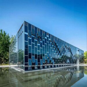
For commercial project teams that need to advance beyond rack-mounted systems into truly integrated building solutions, Jia Mao BIPV engineers solar products that function simultaneously as weather barrier, structural element, and power generator. With a 3 GW annual production capacity, monocrystalline cells exceeding 22% efficiency, and a product portfolio spanning transparent solar panels, BIPV roofing panels, photovoltaic glass, and solar inverters, the company serves EPC contractors, curtain-wall fabricators, and commercial developers who need custom dimensions, specific colour specifications, and module-level electrical documentation to meet AHJ requirements. Their POE-encapsulated glass-glass modules carry a 25-year performance guarantee and meet B1-grade flame-retardancy standards — qualifications that matter when a module is part of the building envelope, not just mounted on top of it.
Glossary of Key Technical Terms
The Design Decisions That Define a Truly Solar-Ready Roof
A solar-ready commercial roof is not a roof with a reserved zone on a drawing. It is a roof where the structural engineer has confirmed load capacity, the membrane manufacturer has approved the mounting detail, the electrical design has coordinated conduit routing and service entrance capacity with the utility, and the commissioning plan is written before the first module arrives on site. The difference between these two definitions is approximately 15–25% of total solar project cost — the amount that typically disappears in change orders, structural upgrades, and interconnection delays when integration planning is left until the PV vendor is engaged post-construction.
For commercial real estate developers, facility managers, and EPC contractors operating in a market where ESG commitments are now contract-level obligations rather than aspirational targets, the return on integrated solar design is measurable and increasingly well-documented. A warehouse portfolio operator in the Pacific Northwest documented $2.3M in total project cost avoidance across six facilities that were designed as solar-ready from day one, compared with three comparable facilities where solar was added post-construction. The avoided costs included structural reinforcement ($420K), conduit re-routing ($310K), membrane penetration re-work ($185K), and interconnection delay carrying costs ($1.4M).
The industry is also moving toward truly integrated solar building envelopes — not just panels on roofs, but solar glass in skylights, solar cladding on facades, and BIPV roofing panels that eliminate the membrane-plus-racking two-layer system entirely. For project teams ready to explore that frontier, providers like Jia Mao BIPV’s integrated module portfolio offer a starting point for specification-level technical dialogue before the design development phase closes.
The next steps are clear: engage your structural engineer and roofing consultant before schematic design is complete, request an interconnection pre-application review from your utility before permit submission, and specify conduit sleeves and equipment pads in the base building contract even if PV installation is deferred. These three actions alone eliminate the majority of the avoidable costs and timeline delays that have characterised commercial solar retrofits for the past decade.


-300x300.jpg)