Advanced Solar Roof Tile Maintenance & Optimization Guide
Strategic Insights for Industry Professionals – Contractors, EPCs, Architects & Distributors
The difference between a 25-year revenue stream and a 25-year warranty dispute comes down to what happens between commissioning and year 10.
What This Guide Covers:
This is not a general solar panel cleaning article. It is a field-tested operational framework for the professionals who carry long-term performance liability on commercial solar roof tile systems: curtain wall and roofing contractors, photovoltaic EPC firms, building material distributors, architects, and design consultants.
Every section addresses a specific maintenance failure mode that occurs on real commercial projects, with the protocols that prevent it from becoming an expensive problem.
The operational reality: well-maintained solar roof tile systems retain 95% of their original output capacity after 20 years. Poorly maintained systems drop to 85% or lower. For a 500 kW commercial rooftop, that 10-percentage-point gap represents roughly $180,000–$240,000 in lost energy value over the system’s lifetime at a $0.14/kWh commercial rate — before accounting for warranty disputes and unplanned repair costs.
1. Executive Summary: Elevating Solar Roof Performance Through Proactive Management
The Maintenance Gap Nobody Advertises
Solar roof tile installation is a competitive, margin-compressed market. Operations and maintenance, on the other hand, is a relationship-based business where clients evaluate you not at ribbon-cutting but at years 5, 10, and 15. EPC firms and specialized contractors who build systematic O&M capability into their service model are building something that purely installation-focused competitors cannot quickly replicate: a verifiable track record of long-term performance.
This guide delivers actionable intelligence across three dimensions:
- Inspection protocols — what to check, when, and with what tools to reduce liability exposure and maintain warranty coverage
- Performance optimization — how to squeeze maximum energy yield from installed systems through monitoring, tuning, and electrical health management
- Stakeholder coordination — how to define responsibilities in advance so that when something goes wrong, the response is swift and the warranty claim holds up
Who This Guide Is Written For
Curtain wall and roofing general contractors managing multi-year installation and maintenance commitments. Photovoltaic EPC and energy service providers running O&M portfolios across multiple commercial sites. Building material brands and distributors whose clients face technical questions post-installation. Architects, consultants, and design institutes specifying systems that must perform over a 25-year building lifecycle.
If you are in any of these roles and you have solar tile systems in the field right now, every section of this guide has a direct application to your current portfolio.
2. Seasonal Inspection Framework for Solar Roof Tiles
A structured seasonal inspection routine prevents degradation and ensures compliance with warranty and code standards.
Biannual professional inspections are the commercial standard — typically April and October — supplemented by quarterly visual checks and post-event assessments after any significant weather. According to Colite Tech’s commercial solar maintenance guide, quarterly visual inspections are specifically recommended for high-dust or coastal installations.
Here is what each season demands in practice:
Spring: Post-Winter Assessment and System Reset
Spring inspection is the most consequential of the year because it establishes your baseline before the peak generation period. Winter creates conditions that accumulate damage gradually — freeze-thaw cycles at sealant joints, debris loading from wind events, and ice formation at tile edges that can lift flashing details.
Conduct a full thermal drone inspection using an infrared camera — thermal imaging uses heat-sensitive cameras to detect temperature differences across the panel surface, revealing hotspots, delamination, and bypass diode failures invisible to the naked eye. Any tile zone running 8–15°C hotter than adjacent panels under the same irradiance is flagging a developing failure.
Clear all organic debris from tile valleys, gutters, and perimeter zones. Inspect sealant joints at all five critical interface points: perimeter flashing, ridge cap integration, conduit penetrations, tile-to-tile joints, and structural support connections.
Summer: Thermal Load Management and Hotspot Verification
Summer brings peak irradiance and peak thermal stress. The primary summer risk for commercial solar tile systems is inverter thermal shutdown — when inverter operating temperature exceeds the manufacturer’s design limit, the unit de-rates output or shuts down to protect itself. An inverter logging more than one thermal shutdown per quarter is operating outside its design envelope and requires corrective action before the cooling system fails under load.
Conduct a targeted thermal imaging review of any zones flagged during spring inspection. Verify that inverter ventilation pathways are clear of dust accumulation — a blocked ventilation filter can increase inverter internal temperature by 12–18°C, cutting effective inverter life by 25–40%.
Review monitoring data weekly during peak summer months to catch string output deviations early, before they compound across a full high-generation season.
Fall: Pre-Storm Readiness and Drainage Clearance
Fall inspection focuses on preparing the system for winter loading rather than identifying summer-generated degradation. Clear all drainage pathways — gutters, roof valleys, and tile channel runs — of leaf accumulation and organic debris before the first freeze. Standing water at tile edges that freezes expands against sealant joints and accelerates degradation at exactly the interfaces most vulnerable to moisture ingress.
Inspect all mechanical fasteners at perimeter flashing details for signs of corrosion or loosening. Check that bird guard mesh is intact at array perimeter zones — fall is the season when nesting material accumulates most aggressively.
Winter: Load Monitoring and Output Management
Winter inspection for most commercial solar tile portfolios is a monitoring-intensive season rather than a hands-on maintenance season. Focus on two specific risks:
Snow load accumulation: For installations in ASCE 7 snow zones 3–7, track real-time roof load monitoring if the system incorporates load cells. Without load cells, apply the structural engineer’s conservative allowable snow accumulation depth as the trigger for manual snow removal — never walk on solar tiles; use a roof rake from the perimeter.
Output monitoring during partial shading events: Snow covering a portion of the array — common at eave lines and areas downslope from rooftop HVAC units — creates the classic partial shading performance collapse, where a shaded cell reverse-biases and pulls down the entire string. Verify that bypass diodes are functioning in modules installed in shading-prone zones by comparing string-level monitoring data before and after partial snow coverage events.
| シーズン | Primary Focus | Tools Required | Interval |
|---|---|---|---|
| 春 | Damage assessment, thermal scan, sealant inspection | Drone IR camera, sealant probe, megohmmeter | Once (April) |
| 夏 | Hotspot verification, inverter thermal check | Drone IR camera, clamp meter, monitoring dashboard | Weekly monitoring; site visit if alert |
| 秋 | Drainage clearance, flashing check, debris removal | Roof rake, visual inspection kit, moisture meter | Once (October) |
| 冬 | Load monitoring, output tracking, shading analysis | Remote monitoring dashboard, load cells where installed | Continuous monitoring |
| Post-Storm | Impact damage, debris penetration, displacement check | Drone camera, visual inspection | After any event >70 mph wind |
3. Performance Optimization: Engineering Efficiency into Daily Operations
Maximizing energy yield requires more than installation — it demands intelligent system tuning.
The Shading Problem on Complex Roof Geometries
Standard string inverter wiring assumes all modules in a string receive roughly equal irradiance. On commercial buildings with complex roof geometries — multiple pitches, parapet walls, rooftop HVAC equipment, and adjacent structures — this assumption fails routinely. A single shaded cell in a string can reduce that entire string’s output by 30–50%, not just the shaded cell’s contribution.
Micro-inverters (a device mounted behind each individual module that converts DC to AC at the panel level) and DC optimizers (module-level DC-to-DC converters that maximize each panel’s output before feeding a central inverter) both solve this problem by decoupling each module’s electrical behavior from the rest of the string.
その SunSup PV optimizer comparison guide documents that MLPE (Module-Level Power Electronics) equipment recovers 15–25% of shading-related losses in complex commercial roof configurations compared to standard string wiring. For a 200 kW system in a partially shaded urban installation, that recovery represents roughly $8,400–$14,000 in additional annual energy value.
Monitoring Platform Integration: What “Real-Time” Actually Means
Modern commercial monitoring platforms — including SolarEdge, Enphase Enlighten, and SCADA systems compliant with IEC 61724 solar monitoring standards — provide irradiance-normalized output data updated every 5–15 minutes at the string or module level.
The critical capability is not just data collection — it is irradiance-normalized comparison: the system alerts when output drops relative to expected output given current solar conditions, not just when absolute output drops. This distinction prevents nuisance alerts on cloudy days and ensures that a real hardware fault on a partly cloudy afternoon is not masked by a simple “low production” notification.
Glossary Term — Performance Ratio (PR): The ratio of actual energy output to theoretically possible output given the irradiance received. A healthy commercial solar tile system should maintain a PR of 0.75–0.82. A PR declining below 0.70 over a rolling 30-day period indicates a systematic problem warranting immediate investigation. Systems with PR consistently above 0.80 are well-optimized. Heaven Green Energy’s Performance Ratio explainer provides a useful reference definition for client communications.
Tilt, Azimuth, and Post-Installation Verification
The tilt and azimuth angles specified during the design phase directly determine annual energy yield. A south-facing 30° tilt in a temperate northern hemisphere location captures approximately 15–20% more annual irradiance than an east or west-facing 30° tilt at the same location. Deviations from the design specification caused by installation tolerances, structural constraints, or field-driven layout changes can represent a permanent performance deficit that no amount of O&M intervention will recover.
For projects where installation accuracy is critical — high-value BIPV installations, performance-guaranteed systems, or systems claiming LEED energy credits — conduct a drone-based LiDAR scan within 30 days of commissioning to verify as-installed tilt and azimuth against the design specification. Deviation greater than 3° from the specified azimuth should be flagged as a design non-conformance and documented in the as-built record.
4. When to Escalate: Critical Triggers for Installer Intervention
Timely escalation prevents minor issues from becoming structural or financial liabilities.
Not every performance deviation requires an emergency field response. The skill that separates high-performing O&M teams from reactive ones is knowing precisely which conditions demand immediate escalation versus which warrant scheduled investigation.
Trigger 1: Persistent Underperformance — The 15%/Two-Week Rule
A string or system producing more than 15% below its modeled P50 output for two or more consecutive weeks — irradiance-normalized, confirmed on the monitoring platform — is not recovering on its own. Intervene. The two-week threshold eliminates weather-driven fluctuations while catching hardware failures, soiling events, and developing faults early enough that the repair cost remains manageable.
A field team dispatched after two weeks of confirmed underperformance typically finds and fixes the issue for $300–$1,200. The same issue discovered after four months of underperformance costs $900–$3,500 in repair plus $3,000–$9,000 in unrecoverable production loss — and may have already triggered a client inquiry that starts from a position of eroded trust.
Trigger 2: Physical Damage — The Zero-Tolerance Indicators
Three physical conditions require immediate escalation regardless of whether monitoring is showing a corresponding output drop, because they represent structural integrity and waterproofing risks that progress faster than monitoring can detect:
Visible tile cracking: Any crack extending more than 25 mm from a tile edge, or any crack that crosses the cell layer (visible as a discontinuity in the color of the active area), requires immediate isolation of the affected module and replacement within 30 days. Cracked tiles allow moisture infiltration to the laminate boundary, accelerating edge seal failure and creating a pathway for water ingress to the roof deck.
Delamination at laminate boundaries: Separation between the glass layers or between the cell layer and the encapsulant — visible as bubbling, cloudiness, or whitish opacity at the tile surface — creates an uneven thermal mass that drives accelerated thermal cycling stress on the cell layer. The Movitherm solar thermal imaging guide identifies delamination as one of the most reliably detected fault signatures in IR imagery, appearing as a distinctive mottled thermal pattern.
Water ingress at flashing interfaces: Any visible water staining, efflorescence, or active water penetration at a roof-to-wall junction, ridge cap transition, or conduit penetration point is an immediate intervention trigger. Refer to the moisture protocol in Section 3 of this guide for the remediation sequence.
Trigger 3: Recurring Electrical Faults — The Pattern That Precedes Failure
A single ground fault alarm in a commercial solar tile system typically indicates a localized insulation issue — a pinched wire, a developing connection corrosion, or moisture contact at a junction box seal. It warrants investigation within 72 hours.
A second ground fault alarm within 90 days at the same or an adjacent string location is no longer a localized anomaly. It is a pattern indicating systematic electrical degradation — corroding conduit, water ingress at a junction box, or a developing arc fault condition. Escalate to a licensed electrical contractor with NEC Article 690 experience within 24 hours. Do not reset and monitor: recurring ground fault alarms in the same system zone are the documented precursor to NEC 690.11 arc fault conditions.
5. Contractor Coordination Protocols for Multi-Trade Projects
Solar roof tiles require seamless integration between roofing, electrical, and façade teams.
The Pre-Installation Alignment Meeting
Every commercial solar tile project involving more than one trade — which is every project — requires a pre-installation alignment meeting between the roofing general contractor, the PV specialist or EPC, the structural engineer, and the building owner’s representative. This is not a courtesy. It is the single intervention most consistently cited by experienced EPC firms as the factor that determines whether a multi-trade solar tile installation proceeds smoothly or generates change orders, delay claims, and warranty ambiguities.
The meeting agenda should cover four specific items: the roofing waterproofing installation sequence relative to conduit penetration and flashing installation; the structural load distribution plan confirming that solar tile dead loads are transferred to the framing in the locations the structural calculation assumed; the electrical rough-in sequence confirming conduit pathways, junction box locations, and grounding conductor routing; and the commissioning hold point where the roofing contractor signs off before the PV electrical team proceeds with final string wiring.
Without this meeting, the typical failure mode is a 3–6 week project delay caused by conduit routing that conflicts with roofing details, junction box locations that require flashing modification, or electrical rough-in that precedes the waterproofing installation and then requires partial re-work to restore the waterproofing sequence.
Defining the Responsibility Boundary in Writing
The single most common cause of warranty disputes in multi-trade solar tile projects is a missing or ambiguous boundary definition between the roofing warranty and the PV system warranty. The two warranty scopes overlap at exactly the points most likely to generate claims: tile installation and mounting hardware, flashing at the tile perimeter, and conduit penetrations.
Define the boundary in the contract documents with this level of specificity: the roofing contractor is responsible for waterproofing integrity at all penetrations, with signed acceptance of each penetration before the PV electrical team installs conduit; the PV contractor is responsible for the electrical performance of all components from the junction box outward; and both parties jointly bear responsibility for inspection and sign-off at the tile-mounting-to-flashing interface before tile installation proceeds.
BIM Coordination for Curtain Wall and Complex Façade Integration
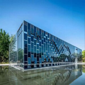
For projects integrating solar tiles with unitized curtain wall systems — a growing application for commercial high-rise and institutional buildings — BIM (Building Information Modeling) coordination is not optional. Curtain wall anchor systems, structural mullion positions, and drainage channel locations must be resolved in the federated digital model before fabrication, because curtain wall panel modifications after fabrication carry 8–18 week lead time penalties that can delay the entire project.
その Jia Mao BIPV BIPV curtain wall design resource provides detailed guidance on integrating BIPV glass panels with standard curtain wall framing systems, including electrical routing within curtain wall mullion cavities, junction box pocket sizing requirements, and drainage plane compatibility with standard curtain wall drainage details.
Clash detection between solar tile mounting hardware and curtain wall anchors should be resolved in the BIM model at the design development phase — typically 18 months before installation — not in the field during installation.

Early BIM coordination between roofing, structural, and PV teams eliminates the field conflicts that turn into change orders.
6. Design & Specification Best Practices for Architects and Consultants
Precision in design directly impacts long-term serviceability and compliance.
Wind Uplift and Seismic Specification
Specify solar tile products using wind uplift test data that matches the actual wind exposure category of the building, not the manufacturer’s maximum rated wind speed. A tile rated for 110 mph exposure in a standard exposure category B suburban context is not automatically qualified for the same building in a coastal exposure category D environment — the design wind pressure in exposure D at the same basic wind speed is substantially higher.
For buildings in seismic design categories C through F, require PE-stamped structural calculations for the solar tile mounting system that address both lateral forces and differential movement at the connection to the roof structure. Standard residential-scale installation calculations are not adequate for commercial buildings in high-seismic zones.
The relevant standards for specification: ASCE 7-22 for wind and seismic load determination; IBC Chapter 15 for roof assembly requirements; NEC Article 690 for electrical system compliance.
Thermal Movement in Large Arrays: Specifying the Right Expansion Allowance
A 60-meter continuous run of solar tiles on a commercial roof will experience a temperature differential between winter minimum and summer maximum of 50–70°C in most North American and European climates. Aluminum framing at that temperature differential expands and contracts by approximately 4.1 mm per 10 linear meters — so a 60-meter aluminum frame run will move roughly 24 mm between seasonal extremes.
Standard tile mounting details that do not provide for this movement will either crack the tile at the fixed end or pull the mounting detail apart at the free end within the first 3–5 thermal cycles. Specify sliding clip connections at regular intervals (maximum 3 meters) in large tile arrays, and include expansion joints at intervals consistent with the manufacturer’s framing specifications — typically every 10–12 linear meters for aluminum framing systems.
Third-Party Testing Documentation: What to Actually Request
Do not accept marketing-grade certification claims. Request the following documents for every solar tile system specified on a commercial project:
| Document | Issuing Body | What It Confirms |
|---|---|---|
| IEC 61215 test report | Accredited laboratory (TÜV, Bureau Veritas, Intertek) | Electrical performance and durability under climate stress |
| IEC 61730 safety test report | Same as above | Electrical safety and shock/fire protection |
| UL 1703 listing (US projects) | UL LLC | Module safety for US code compliance |
| ASTM E108 / UL 790 fire test | Accredited fire laboratory | Class A fire rating of the complete tile assembly |
| Wind uplift test report | Accredited laboratory | Specific wind load capacity at stated fastener spacing |
| Thermal cycling test (IEC 61215-2) | Same as IEC 61215 body | Sealant and frame integrity under temperature differential |
Request test reports for the exact product configuration specified — including glass thickness, cell type, and frame dimensions — not just a generic product family certification. Manufacturers sometimes certify a representative configuration and market the entire product range under that certification; verify that the specific product ordered matches the tested configuration.
7. Distributor & Manufacturer Engagement: Ensuring Supply Chain Reliability
Material availability and technical support are critical to project timelines.
The Lead Time Reality for Commercial Solar Tiles
Custom-specified solar roof tiles — color-matched units, non-standard dimensions, products with specific transparency levels or cell configurations — carry fabrication lead times of 12–20 weeks from confirmed purchase order to delivery. In the context of a commercial construction schedule where the roofing installation sequence is often the critical path for interior fit-out, a surprise lead time extension can cascade into a project delay with significant liquidated damages exposure.
The distributor’s role in managing this risk is not passive warehousing. It is active supply chain monitoring: tracking manufacturer production schedules, communicating lead time changes to the EPC team before they become critical path issues, and maintaining safety stock of standard product configurations in regional warehouse locations.
Ask potential distribution partners three specific questions before award: what is the regional warehouse stock position for the standard tile configurations specified on this project? What is the current factory production lead time for custom configurations, confirmed with the manufacturer this week — not last quarter? And what is the replacement shipping lead time for a failed tile requiring warranty replacement, including expedited shipping if needed?
Matching Non-PV Tiles for Aesthetic Continuity
Every large commercial solar tile installation has areas where PV tiles cannot or should not be placed: below minimum irradiance thresholds, in fire setback zones, or in architectural zones where tile exposure conflicts with PV performance requirements. These areas require non-PV tiles that match the solar tiles in color, profile, surface texture, and dimensional tolerances.
A distributor who cannot supply matching non-PV tiles from the same manufacturer is forcing the roofing contractor to source from a different supplier — creating installation sequence coordination problems, potential warranty boundary disputes, and, in the worst case, a visible aesthetic mismatch that no amount of explanation satisfies a building owner.
Confirm matching non-PV tile availability as a qualification criterion before awarding distribution supply agreements for solar tile projects.
Technical Documentation Package: Pre-Bid Requirements
Require suppliers to provide the following technical documentation at or before the bid stage — not after award:
- Full technical datasheets for the specified tile configuration including dimensions, weight, electrical specifications at STC, and installation torque values
- CAD installation details in DWG or DXF format compatible with project drawings
- Revit BIM family file for the specified product (increasingly available from major manufacturers, including Jia Mao BIPV’s product range)
- Fire rating documentation for the complete assembly including underlayment and mounting system
- Warranty document — the actual warranty, not the marketing summary — reviewed by the owner’s legal team before contract execution
8. EPC and Energy Service Provider Oversight: Managing System Health at Scale
For portfolio owners, consistent performance metrics drive O&M profitability.

A SCADA dashboard that monitors 40 systems simultaneously is the infrastructure that makes O&M profitability possible at portfolio scale.
Automated Alert Systems: The Configuration That Actually Works
An alert system configured to notify a generic operations inbox when any deviation occurs is not a monitoring program. It is a noise generator that trains technicians to ignore alerts. Configure automated alerts against two specific thresholds that are calibrated for commercial solar tile systems:
String output deviation >5% from modeled P50 — irradiance-normalized, sustained for more than 24 hours. This threshold catches real hardware issues while filtering out weather-driven fluctuations and cloud transients. Alert delivered to a named technician with 24-hour acknowledgment requirement.
Single module deviation >15% from adjacent modules — under equivalent irradiance conditions. This threshold catches module-level failures — a failed optimizer, a developing cell crack, a corroding junction box connection — before they propagate to string-level impact. Alert delivered to the site O&M lead with a 72-hour field investigation requirement.
Do not configure alerts for absolute output values on cloudy days, for minute-by-minute fluctuations, or for inverter communication dropouts shorter than 15 minutes (these are almost always network issues, not hardware failures). Alert fatigue — the condition where technicians stop treating alerts as meaningful because too many are false positives — is the primary reason monitoring systems fail to deliver their design value.
Standardizing Inspection Checklists Across Projects
An EPC firm managing 20+ commercial solar tile systems across multiple contractors and geographic markets faces a data consistency problem: if every site uses a different inspection form, the portfolio-level performance analysis is based on incomparable data.
Develop a standard inspection checklist that applies across all sites in the portfolio, with site-specific addenda for locally relevant conditions — coastal salt-air exposure, high-seismic zone grounding requirements, snow load monitoring requirements. The standard checklist ensures that IR test results, PR calculations, and physical inspection findings are directly comparable across sites, enabling the portfolio-level failure pattern analysis described in Section 9 of this guide.
Benchmarking PR Monthly: The Portfolio KPI That Catches Drift
Performance Ratio is the single most reliable portfolio-level health indicator for commercial solar tile systems. Unlike absolute kWh output — which varies with weather and seasonal irradiance — PR is weather-normalized, making it directly comparable across months and across geographically dispersed sites.
Calculate PR monthly for every system in the portfolio using metered irradiance data (from a pyranometer mounted on the roof, not from a satellite irradiance model — satellite data introduces systematic errors of 5–15% that contaminate PR calculations). Track PR as a rolling 12-month average to filter seasonal noise. Any system showing a sustained PR decline of more than 0.5 percentage points per year (from a baseline established at commissioning) is experiencing degradation beyond the expected 0.5%/yr module aging rate and warrants investigation.
9. Warranty Management and Documentation Compliance
Proper documentation preserves warranty coverage and limits liability exposure.
Why Warranty Claims Actually Fail
The most common reason a legitimate warranty claim on a commercial solar tile system is denied is not that the manufacturer is unresponsive or acting in bad faith. It is that the claimant cannot demonstrate that the system was maintained in accordance with the manufacturer’s requirements during the period leading up to the failure.
Maintenance performed but not documented is — from the manufacturer’s warranty administration standpoint — maintenance that was not performed. The EPC contractors and specialized roofing firms who consistently process successful warranty claims are the ones who maintain digital maintenance records with timestamped entries, geo-tagged photographs, and technician certification references. The firms who lose claims are the ones who kept paper logs in a site folder — or kept no records at all — and cannot reconstruct the maintenance timeline when a claim reviewer asks for it.
The Digital Maintenance Record: Minimum Required Fields
Every maintenance visit must generate a digital record containing these elements:
| Record Element | Why It Matters for Claims | Acceptable Format |
|---|---|---|
| Date, time, technician name | Establishes timeline of documented care | Timestamped digital log entry |
| GPS/geo-tagged site photographs | Confirms location and condition at time of service | Photo with embedded metadata |
| Technician certification reference | Proves qualified personnel performed service | NABCEP or electrician license number |
| Specific actions performed | Demonstrates adherence to OEM maintenance protocol | Structured checklist + narrative |
| Equipment tested and results | Provides diagnostic baseline for warranty comparison | Test report with values and pass/fail |
| Deferred items and planned resolution | Shows awareness and corrective action plan | Action item list with target dates |
Cleaning Methods That Won’t Void Coverage
Most solar tile manufacturers — including Jia Mao BIPV — specify cleaning with deionized or purified water and soft-bristle brushes or non-abrasive pads. High-pressure washing is explicitly prohibited in most warranty documentation because it can force water under tile edge sealants, crack anti-reflective surface coatings, and damage junction box seals.
If a cleaning method is not explicitly listed in the manufacturer’s warranty documentation as approved, do not use it. Submit a written request to the manufacturer’s technical support team before using any cleaning equipment or chemical product not on the approved list. Keep the manufacturer’s written response in the maintenance record file — it becomes documentary evidence of approved method compliance if a moisture-related claim arises.
Tracking Labor and Material Warranties Separately
A commercial solar tile installation typically involves three distinct warranty instruments that do not run on the same timeline: the module performance warranty (typically 25 years from the manufacturer), the installation labor warranty (typically 2–5 years from the installing contractor), and the building envelope waterproofing warranty (typically 10–20 years from the roofing contractor). These warranties can overlap, and the overlap zones — particularly at tile-to-flashing interfaces — are where root cause attribution in a claim becomes disputed.
Track each warranty instrument separately in your project management system with the specific expiration dates, coverage scope, and manufacturer/contractor contact for each. When a claim arises, begin root cause attribution before contacting either warranty holder — a thermal image, a moisture scan, and a commissioning record that establishes the pre-failure condition is worth more in warranty negotiation than either party’s field technician’s opinion.
10. Future-Proofing: Integration with Smart Building and Grid Services
Solar roof tiles are not standalone products — they are energy assets.
Designing for BESS Integration from Day One
A commercial solar tile system that was designed with battery storage as an afterthought will cost significantly more to retrofit than one designed for storage from the beginning. The key design decisions that determine retrofit cost are not the tile selection — they are the electrical system architecture: AC coupling point location, available space in the electrical room for battery racks and bidirectional inverters, conduit pathway sizing, and structural capacity on the floor below the planned battery location.
BESS (Battery Energy Storage System): A battery-based energy storage installation connected to the solar system that stores excess daytime solar generation and dispatches it during peak-price hours or grid demand events. Typical commercial BESS units weigh 150–300 kg per module and require structural floor loading assessment before installation.
Make three design decisions at project outset — not during the next project phase — that enable future storage integration: size the electrical room for 150% of the initial inverter footprint; install dedicated conduit sleeves from the roof electrical infrastructure to the ground-floor electrical room even if they are not initially used; and specify bidirectional-capable inverters or specify inverters with a documented upgrade path to storage-ready firmware.
Demand Response and API-Enabled Inverter Configuration
Modern commercial solar inverters from major manufacturers — including SolarEdge, Fronius, and SMA — support open API connections that allow third-party building energy management systems to read real-time generation data and, in some configurations, adjust inverter output in response to building demand signals.
Demand response refers to a building owner’s agreement with the utility to voluntarily reduce electricity demand or shift load during peak grid demand periods, in exchange for financial incentives — typically $50–$150 per kW of available demand response capacity per year on commercial accounts. A solar tile system with API-enabled inverters and on-site storage is a demand response asset. A system with a closed-protocol inverter is not, regardless of its generation capacity.
Specify inverters with documented API capabilities and utility-compatible demand response protocols at the design stage. Retrofitting API connectivity to an inverter installed without it typically requires firmware upgrades that are not always available and hardware replacements that are never inexpensive.
Net-Zero and LEED Certification Strategy
Solar roof tiles are specifically recognized as a building-integrated renewable energy system in LEED v4.1 BD+C under the Renewable Energy credit (up to 5 points). For projects pursuing LEED certification, the solar tile system energy contribution needs to be modeled in the energy simulation (typically EnergyPlus via the OpenStudio workflow) and the modeled generation verified against monitored production data in the LEED documentation package.
Position solar tile systems as part of the building’s net-zero energy strategy — not as a standalone feature — by connecting the system’s modeled energy contribution to the building’s total energy use intensity target. This framing makes the solar tile specification a building performance decision rather than a discretionary add-on, which changes both the client’s budget commitment and the architect’s specification confidence.
For EPC firms pursuing Energy Performance Contracting models — where the EPC guarantees a defined level of energy savings and receives compensation based on verified performance — solar tile integration with monitoring and smart building systems transforms a discretionary product into a contractually performable energy asset.
Watch: Solar Roof Tile Performance and Maintenance in Practice
Click to watch: A practical comparison of solar tile and panel performance, including shading response, inverter selection, and long-term output management — directly applicable to commercial O&M decisions.
25-Year Financial Model: Maintenance Approach Comparison
The following table compares three maintenance approaches on a 200 kW commercial solar tile system installed at $320,000, generating approximately $42,000 in annual energy value at $0.14/kWh.
| Maintenance Approach | Annual O&M Cost | Year 10 Output | Year 20 Output | Cumulative Unplanned Repairs (25 yr) | Net 25-Year Energy Value |
|---|---|---|---|---|---|
| No structured maintenance | $0/yr | ~82% | ~71% | $45,000–$80,000 | $740,000 |
| Reactive only (fix on failure) | $3,500/yr | ~87% | ~78% | $28,000–$45,000 | $860,000 |
| Proactive O&M (this guide’s protocol) | $8,500/yr | ~94% | ~89% | $8,000–$15,000 | $1,080,000 |
Assumptions: 0.5%/yr degradation for maintained systems; 0.8%/yr reactive; 1.1%/yr no maintenance. Utility rate escalation 3%/yr. Project-specific analysis required.
The proactive maintenance program costs approximately $125,000 more in O&M fees over 25 years. It generates approximately $340,000 more in energy value. Net benefit: ~$215,000 per 200 kW system — before accounting for warranty protection value, avoided emergency repair costs, and client retention.

A well-maintained solar roof tile system at year 15 looks and performs like a year-5 system — because the O&M program treated it as the energy asset it is.
Glossary of Key Terms
AFCI (Arc Fault Circuit Interrupter): A protective device required under NEC 690.11 that detects dangerous electrical arcing in DC circuits and disconnects the circuit before the arc can ignite surrounding materials.
BESS (Battery Energy Storage System): An assembly of battery cells, power conversion equipment, and control systems that stores electrical energy and can discharge it on demand.
BIM (Building Information Modeling): A digital process in which all project stakeholders work from a shared three-dimensional model of the building, enabling clash detection and coordination before construction.
DC Optimizer: A module-level DC-to-DC converter that maximizes each panel’s output independently, reducing shading losses in partial shade conditions.
EL Imaging (Electroluminescence Imaging): A quality inspection technique that passes current through a solar cell in the dark and photographs the resulting light emission, revealing micro-cracks and cell defects invisible to visible-light photography.
MLPE (Module-Level Power Electronics): The category encompassing both micro-inverters and DC optimizers — devices that manage power conversion or optimization at the individual module level rather than the string level.
Performance Ratio (PR): A dimensionless metric (0–1 scale) expressing the ratio of actual energy output to the theoretical maximum given the irradiance received by the system. A PR of 0.75 means the system is delivering 75% of its theoretical maximum.
Rapid Shutdown: A requirement under NEC 690.12 that PV system conductors on a building must be de-energized to safe voltage levels within 30 seconds of a shutdown initiation signal, protecting emergency responders.
SCADA (Supervisory Control and Data Acquisition): A software architecture that collects real-time performance data from distributed energy systems and presents it in a centralized monitoring and control interface.

Technical support from a knowledgeable distributor — available before bid and after installation — is what separates a supply chain partner from a commodity supplier.
よくある質問
1. How often should solar roof tiles be inspected on commercial or multi-family projects?
The professional standard for commercial solar tile systems is biannual professional inspections — typically April and October — combined with quarterly visual inspections and a post-storm assessment after any weather event producing sustained winds above 70 mph. Coastal and high-humidity installations add an annual insulation resistance test to the biannual schedule. The April inspection is the highest-priority visit of the year because it establishes your system health baseline before the peak summer generation period.
2. What are the most common causes of solar tile underperformance in northern climates?
Three causes account for the majority of northern climate underperformance events: snow coverage and accumulation at array downslope edges and eave lines (reducing string output by 30–100% on affected strings during coverage periods); micro-shading from debris accumulation — leaves, ice, and organic material — at tile valleys and perimeter zones; and suboptimal string design that places shading-prone tiles in series with unshaded tiles, causing the weakest-performing tile to pull down the entire string’s output. All three are preventable through proper fall preparation, pre-winter debris clearance, and MLPE equipment specification at design stage.
3. Can solar roof tiles be integrated with unitized curtain wall systems?
Yes, with the right coordination sequence. BIPV glass tiles are increasingly integrated with unitized curtain wall systems on commercial high-rise and institutional projects. Successful integration requires: early BIM coordination between the curtain wall fabricator and the PV EPC to resolve anchor conflicts and drainage compatibility before fabrication; electrical routing planned within curtain wall mullion cavities with junction box pockets incorporated into the curtain wall unit design; and a defined installation sequence that places electrical rough-in before panel installation rather than after. The Jia Mao BIPV curtain wall integration guide provides specific dimensional and electrical routing requirements for curtain wall integration projects.
4. Do solar tiles meet Class A fire ratings when used on high-rise buildings?
Only specific certified assemblies meet Class A fire ratings — and the rating applies to the complete assembly (tile, mounting system, underlayment, and deck), not to the tile alone. Verify by requesting ASTM E108 and UL 790 test reports for the complete assembly configuration specified on the project. For buildings over 40 feet in height, NFPA 285 fire propagation testing is also required for the complete facade assembly in most US jurisdictions. Do not accept a tile-only fire rating certification as evidence of assembly-level compliance.
5. How do I handle warranty claims when roofing and PV performance issues overlap?
Begin with root cause documentation before contacting either warranty holder. A thermal image of the affected zone, a moisture scan of the roof deck in the area, and a commissioning report establishing pre-failure baseline conditions together enable a root cause attribution analysis that is far more defensible than competing field technician opinions. Once root cause is established, the applicable warranty is clear: if the root cause is water ingress at a flashing detail, the roofing warranty applies; if the root cause is a module manufacturing defect, the product warranty applies; if the root cause is an installation practice issue, the labor warranty applies. Clear commissioning logs and defined responsibility boundaries — established before any claim arises — are the documents that make this attribution straightforward.
6. What cleaning methods are safe for solar tiles without voiding manufacturer warranties?
Deionized or purified water with soft-bristle brushes or non-abrasive microfiber pads is the universally accepted method across major solar tile manufacturers. High-pressure washing is prohibited by most manufacturers’ warranty conditions because it can force water under tile edge sealants, crack anti-reflective surface coatings, and damage junction box seals. Never use acidic or alkaline cleaning solutions unless they are explicitly listed on the manufacturer’s approved cleaning products list. If using a robotic cleaning system, confirm in writing with the manufacturer that the specific robot model is approved for use on the tile product before deployment.
7. Are there BIM object libraries available for major solar tile brands?
Yes. Leading manufacturers provide Revit families and IFC-compatible BIM objects for their solar tile products, typically available through their technical documentation portals or via BIM content aggregators such as BIMObject or Arcat. Request BIM files from your distributor or directly from the manufacturer’s technical team at the design development stage — not at the construction documentation phase. Having accurate BIM objects early enables the clash detection and coordination that prevents field conflicts during installation. Manufacturers who cannot provide BIM-compatible objects for commercial projects are not adequately supporting the professional design workflow.
8. How do I size expansion gaps in long runs of solar tile arrays?
Follow the manufacturer’s specific thermal movement specification for the framing system in use — typically 3–5 mm per 10 linear meters, adjusted for the local temperature differential (the range between the coldest winter temperature and the hottest summer roof surface temperature at the project location). For aluminum-framed systems in continental climates with 60–70°C seasonal temperature differentials, plan for approximately 4 mm of movement per 10 linear meters of continuous frame run. Install expansion joints at intervals consistent with the manufacturer’s framing specifications — typically every 10–12 meters — and at all transitions between roof planes, around penetrations, and at building expansion joints.
9. Can solar tiles be retrofitted over existing membrane roofs?
Direct installation over an existing membrane roof is not recommended for most certified solar tile systems, because the tile mounting system requires direct structural connection to the roof deck framing, not to a membrane surface. The membrane’s compression-only load resistance is insufficient for the uplift loads imposed by solar tile mounting hardware under design wind conditions. Most manufacturers require removal of the existing membrane and installation of solar tiles on a verified structural deck, with the waterproofing system designed specifically for the solar tile product. Consult the manufacturer’s installation manual and a licensed structural engineer before specifying a retrofit application.
10. What data should be collected during commissioning to support future O&M?
Eight data sets form the commissioning record that enables effective long-term O&M: IV curves (current-voltage characteristic traces) for every string in the system establishing the electrical baseline; thermal images of the complete array within one week of commissioning recording the initial thermal signature; string-level voltage and current measurements under known irradiance confirming system configuration; insulation resistance test results for all DC wiring establishing the initial electrical insulation baseline; rapid shutdown functional test confirming compliance with NEC 690.12; as-built drawings updated to reflect field changes with module serial numbers mapped to physical locations; monitoring platform configuration documentation including alert thresholds and escalation contacts; and a signed maintenance responsibility matrix defining each party’s obligations for every foreseeable maintenance scenario. This commissioning record becomes the reference document against which every future maintenance finding and warranty claim is evaluated.
11. How do micro-cracks in solar cells affect long-term output, and how are they detected?
Micro-cracks are fractures in the silicon cell layer, typically caused by mechanical stress during shipping, handling, or installation, or by thermal cycling and wind loading during operation. Individual micro-cracks may not immediately reduce output, but over time they propagate under thermal cycling stress, eventually causing cell segments to become electrically disconnected. This reduces the affected cell’s contribution to string output and creates a reverse-bias condition that accelerates degradation in adjacent cells. Detection requires EL (Electroluminescence) imaging — a technique that passes current through the module in darkness and photographs the resulting light emission, revealing inactive cell areas as dark regions. EL imaging is most effectively deployed at incoming quality inspection before installation and at years 5 and 10 as part of the periodic O&M program.
12. What role do building material distributors play in ensuring code-compliant solar roof installations?
Distributors operate as the technical supply chain link between manufacturers and field installation teams, and their documentation responsibilities are specific: they must provide current certifications (not expired test reports), technical datasheets for the exact product configuration specified (not a generic product family document), installation instructions that align with the code edition adopted in the project jurisdiction, and material safety data sheets for all sealants and ancillary products. Distributors who proactively update field teams when manufacturer specifications change — particularly when sealant compatibility requirements, installation torque values, or warranted maintenance procedures are revised — are providing a technical service that directly protects contractors’ warranty exposure.
13. How can EPCs standardize O&M procedures across multiple solar roof projects?
Develop a centralized digital O&M platform — whether a purpose-built solar O&M software or an adapted CMMS (Computerized Maintenance Management System) — that applies a standardized inspection checklist and PR reporting format across all projects in the portfolio. The checklist should include site-specific addenda for locally relevant conditions but maintain a consistent core structure that enables portfolio-level performance comparison. Establish uniform alert thresholds (>5% string deviation, >15% module deviation) and escalation protocols (24-hour acknowledgment for string alerts, 72-hour field investigation for module alerts) that apply across all sites. Review portfolio-level performance data monthly — not just individual site data — to identify geographic failure patterns that inform future specification decisions.
14. Are solar roof tiles suitable for historic building renovations?
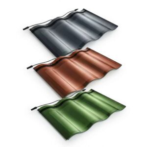
In most jurisdictions, solar panel installations on designated historic structures require review by the local historic preservation authority, and in some cases a Certificate of Appropriateness before installation can proceed. Low-profile solar tile systems — specifically those designed to integrate with existing roofing material profiles — are more likely to receive approval than rack-mounted panels, because they are less visually distinguishable from the surrounding roof surface. Color-matched tile options (terracotta, slate-grey, dark charcoal) further reduce visual impact. Any historic building solar tile project should begin with a pre-application meeting with the relevant historic preservation authority, not a permit submission, to understand the review criteria before committing to a specific product.
15. What liability protections should contractors have when installing integrated solar roofing systems?
Contractors installing integrated solar roofing systems should carry specialized PV installation insurance that explicitly covers the hybrid roofing-plus-electrical scope of work — standard roofing contractor liability policies typically exclude electrical work, and standard electrical contractor policies may exclude roofing waterproofing work. In addition to insurance, maintain NABCEP certification for all solar-specific installation personnel, adhere strictly to the NEC Article 690 requirements in effect in the project jurisdiction, and establish clearly defined scope boundaries in the contract documents that specify which trade holds responsibility for each interface point between the roofing and electrical scopes. Document commissioning results with a third-party commissioning certificate — not just an internal sign-off — to create a defensible record that the system was delivered in code-compliant condition.
Three Actions Before Your Next Project Handover
Before your next commercial solar tile project reaches the commissioning milestone, take these three specific steps:
First, finalize and execute a maintenance responsibility matrix that defines who initiates action, who performs the work, and what documentation is required for every foreseeable maintenance scenario — using the framework in Section 10 as your starting template. Have all parties sign it before handover, not after the first service event.
Second, configure your monitoring platform alerts to deliver string deviation notifications above 5% to a named technician with a defined response protocol — not to a generic inbox. The value of your monitoring investment is realized through the responses it triggers.
Third, request the manufacturer’s complete maintenance protocol documentation — approved cleaning methods, inspection intervals, spare parts specifications, and warranty condition requirements — at project award, not at handover. For projects using Jia Mao BIPV solar glass systems, this documentation is available through their technical support team and defines exactly what constitutes warranty-compliant maintenance over the 25-year coverage period.
The solar tile systems you install today will define your firm’s reputation — positively or negatively — for the next quarter century. The O&M framework you build around them is the investment that determines which direction that reputation runs.