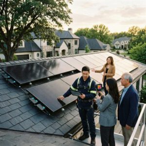

A 48-unit residential development in Zurich completed in 2024 integrated 312 kWp of BIPV across its south-facing facade and 22° pitched roof. The system produces 287,000 kWh per year — covering 68% of the complex’s total electricity demand and shaving CHF 43,000 off the annual utility bill. The project achieved a 7.8-year payback, roughly 40% faster than a comparable retrofit installation on a neighboring building of similar size. The difference was not superior technology. It was design integration from day one.
Building-Integrated Photovoltaics (BIPV) replace conventional building materials — roof tiles, facade cladding, skylights, canopy glazing — with photovoltaic elements that generate electricity while serving their structural and weatherproofing role. Unlike bolt-on panel arrays (BAPV), BIPV becomes the building envelope. When the design team makes solar generation a first-order constraint alongside structural loads, thermal performance, and aesthetics, the resulting system outperforms retrofit alternatives by 15–30% on a levelized-cost-of-energy basis, according to a 2025 IEA-PVPS technical guidebook.
The global BIPV market reached an estimated $30.78 billion in 2026 and is projected to hit $68.12 billion by 2030 at a CAGR of 22% (Research and Markets). That growth is driven overwhelmingly by new construction, where BIPV can be designed in rather than bolted on.
This guide walks through every stage of BIPV integration — from early architectural decisions and shading strategy to electrical design, thermal envelope considerations, commissioning, codes compliance, and long-term monitoring — with the specific goal of maximizing kilowatt-hour output per dollar invested.
Early Design Considerations for BIPV Integration

Aligning Architectural Goals with Energy Targets
BIPV efficiency starts in the schematic design phase — not during construction documentation. The single costliest mistake in BIPV projects is treating solar generation as an add-on after the building form, orientation, and fenestration pattern have been locked. A 2023 study published in Energy and Buildings found that buildings designed with BIPV as a primary constraint produced 22–31% more annual energy per square meter of active surface compared to buildings where BIPV was integrated after the architectural concept was finalized.
The design team should establish a target energy yield (kWh/m²/year) for the BIPV envelope during the programming phase. For a south-facing roof in the U.S. mid-latitudes (35°–42° N), a realistic target for monocrystalline BIPV tiles is 150–200 kWh/m²/year. For semi-transparent facade glazing with 30–40% cell coverage, expect 40–80 kWh/m²/year. These numbers become the benchmarks against which all subsequent design decisions are tested.
Selecting BIPV-Compatible Building Envelope Systems
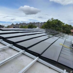
Not every envelope system accommodates BIPV well. Curtain wall systems with unitized panels are ideal for facade integration because each panel arrives pre-assembled with cells, wiring, and weather seals. Stick-built curtain walls can work but increase on-site labor and wiring complexity. For roofing, standing-seam metal roofs and concrete tile substrates are the most forgiving platforms. Membrane roofs on low-slope structures require ballasted mounting or adhesive attachment, which limits BIPV options to lightweight thin-film laminates.
The envelope system must also accommodate the wiring pathways — junction boxes, conduit runs from each BIPV zone to the inverter location, and access panels for maintenance. Specifying these pathways during the envelope design phase avoids the costly field routing that plagues retrofit projects.
Establishing Performance Targets and Modeling Approach
Energy modeling for BIPV uses the same simulation engines as conventional PV — PVWatts, PVsyst, and Polysun — but requires additional inputs for building geometry, shading from neighboring structures, and the thermal interaction between the BIPV element and the building envelope. The model should output at minimum: annual energy yield (kWh), peak power (kW), performance ratio (PR), and specific yield (kWh/kWp). A well-designed new-construction BIPV system achieves a PR of 0.78–0.86; anything below 0.75 signals a design problem worth investigating before construction begins.
Site Orientation and Shading Strategy
Optimizing Main Solar Access Through Layout Planning
Building orientation is the single largest lever for BIPV energy yield. Research published in Renewable Energy (Cheng, 2009) demonstrated that a fixed BIPV system tilted at the latitude angle and oriented due south captures an average of 98.6% of the energy available at the true optimal angle. Deviating from due south by ±15° costs less than 2% of annual yield. But rotating the building 45° east or west from south drops rooftop yield by 8–12%, and a north-facing roof in the northern hemisphere collects only 55–65% of what a south-facing surface receives.
For multi-building developments, site planners should stagger building heights to avoid inter-building shading during peak solar hours (10:00–14:00 solar time). A spacing rule of thumb: the distance between rows of buildings should equal at least 2.5× the height difference between the roofline of the shadowing building and the lowest BIPV surface on the shaded building.
Incorporating Shading Devices and Vegetation Strategies
Intentional shading devices — overhangs, louvers, and brise-soleil — can themselves become BIPV surfaces. A 2025 study in Applied Energy found that adaptive BIPV shading louvers boosted net electricity generation by over 200% compared to static overhangs, reaching up to 6,661 kWh annually on a single south facade of a mid-rise commercial building. These systems reduce interior cooling loads simultaneously, creating a double benefit.
Vegetation — deciduous trees, green walls — should be mapped against seasonal sun paths. Deciduous trees planted southwest of a building provide summer cooling shade while allowing winter solar access after leaf drop. Evergreen plantings should never be placed within the solar window of BIPV surfaces.
Evaluating Seasonal Sun Paths for Year-Round Performance
Sun-path analysis tools like ShadowMap and HelioScope generate hour-by-hour shading maps for every day of the year. For BIPV facades, winter performance matters disproportionately: the sun is low, irradiance hours are few, and any shading during the short solar window has an outsized effect on annual yield. A building in Boston (42° N) receives only 2.5 peak sun hours per day in December versus 6.2 in June — meaning a 30-minute shading event in December eliminates 20% of the day’s generation, while the same event in June costs less than 9%.
Roof and Facade Integration Architecture
Choosing Mounting Options (Static, Tracking, and Semi-Flexible)
New construction gives designers the freedom to select from three BIPV mounting architectures, each with distinct performance and cost profiles.
Static (fixed-tilt) integration is the most common approach. Roof-integrated tiles or facade panels are set at a fixed angle determined by the roof pitch or wall plane. Static systems have no moving parts, minimal maintenance, and a 30–50 year service life. Their limitation is fixed geometry: a panel on a 22° roof in Atlanta (33.7° N) collects about 95% of the energy it would at the optimal 34° tilt.
Tracking-compatible facade louvers use motorized BIPV slats that rotate to follow the sun’s elevation angle throughout the day. The Applied Energy study cited earlier measured a 200%+ yield improvement over static overhangs. However, tracking mechanisms add $40–$80 per square meter in hardware and maintenance costs and introduce mechanical failure points.
Semi-flexible thin-film laminates adhere directly to curved or irregular roof surfaces. They weigh 2–4 kg/m² versus 10–15 kg/m² for glass-glass BIPV tiles, making them suitable for lightweight structures. Their efficiency penalty is significant: 10–15% module efficiency versus 20–24% for rigid monocrystalline BIPV.
Ensuring Seamless Aesthetics and Waterproofing
Waterproofing failures are the primary source of warranty claims in BIPV roofing — responsible for 38% of all post-installation service calls in a 2024 survey of European BIPV installers published by the IEA-PVPS Task 15 program. The solution is multi-layer underlayment with dedicated water-blocking isolation layers on the back of each module, combined with properly lapped flashing at every penetration point — vents, chimneys, ridge caps, and edge transitions.
Color-matched dummy tiles (non-active tiles with the same visual profile as active BIPV tiles) fill areas where wiring runs, structural obstructions, or orientation make active generation impractical. This maintains a uniform roofline while maximizing active surface area where it counts.
Integrating with Non-PV Elements (Vents, Skylights, etc.)
Every roof penetration — plumbing vents, exhaust fans, skylights, HVAC curbs — creates a shading obstacle and a waterproofing challenge. The design should cluster penetrations on the north-facing roof slope (in the northern hemisphere) wherever possible, reserving the south, southeast, and southwest exposures for uninterrupted BIPV surfaces. When penetrations cannot be relocated, the BIPV layout should include a minimum 300 mm clearance zone around each obstruction, with bypass diodes in the affected string to prevent hot-spot formation from partial shading.
Module Selection and System Compatibility
Matching Module Type to Climate and Building Loads
The choice of PV cell technology has a direct impact on yield, especially in hot or overcast climates. The table below compares the three primary BIPV module types across the parameters that matter most for new-construction integration.
| Parameter | Monocrystalline (c-Si) | CIGS Thin-Film | Amorphous Silicon (a-Si) |
|---|---|---|---|
| Module Efficiency | 20–24% | 15–18% | 7–10% |
| Power Density (W/m²) | 180–220 | 130–160 | 60–90 |
| Temperature Coefficient (%/°C) | −0.35 to −0.40 | −0.30 to −0.36 | −0.20 to −0.25 |
| Low-Light Performance | Moderate | Good | Excellent |
| Weight (kg/m²) | 10–15 | 7–12 | 2–5 |
| Transparency Options | 0–50% | 0–30% | 10–40% |
| Typical Degradation (%/year) | 0.3–0.5 | 0.4–0.7 | 0.8–1.2 |
| Cost per Watt (module only) | $0.25–$0.45 | $0.22–$0.35 | $0.18–$0.28 |
| Best BIPV Application | Rooftop tiles, opaque spandrels | Curved facades, canopies | Semi-transparent skylights |
| 25-Year Energy Yield Retention | 87–92% | 82–88% | 72–80% |
Sources: SolarReviews, Greentech Renewables, SolarTech Online.
In hot climates like Phoenix or Dubai, the lower temperature coefficient of thin-film modules partially offsets their lower base efficiency. A monocrystalline panel rated at 400 W STC (25 °C) drops to roughly 370 W at a typical rooftop operating temperature of 55 °C (−0.40%/°C × 30 °C = −12%). A CIGS panel rated at 320 W drops to only 297 W under the same conditions (−0.36%/°C × 30 °C × 320 W), making the gap smaller in practice than it appears on datasheets.
Inverter and Power Electronics Selection
BIPV facades and complex roof geometries create uneven shading patterns that are poorly served by traditional string inverters. Module-level power electronics (MLPEs) — microinverters or DC power optimizers — allow each panel to operate at its individual maximum power point, recovering 5–25% of the energy lost to partial shading on a string inverter system (EnergySage).
For rooftop BIPV with minimal shading, string inverters remain cost-effective at $0.15–$0.25 per watt. For facade applications where adjacent buildings or self-shading create variable irradiance, microinverters ($0.50–$0.70/W) or optimizers ($0.30–$0.45/W) are the defensible choice. The incremental cost pays for itself within 2–4 years through higher yield.
Electrical Code and Building Code Compatibility
In the U.S., BIPV systems must comply with UL 7103 (the unified BIPV standard covering electrical safety, fire, wind, weather, impact, and durability), as well as NFPA 70 (NEC) Article 690 for PV systems and Section 690.12 for rapid shutdown. The NEC 2023 rapid-shutdown requirement mandates voltage reduction to ≤30 V outside the array boundary and ≤80 V inside within 30 seconds. Microinverter-based BIPV systems comply inherently; string-inverter systems require additional MLPEs or UL 3741–listed hazard control systems.
Fire classification must meet UL 790 / ASTM E108 Class A for all roof-integrated BIPV. Facade-integrated BIPV must comply with local fire-spread requirements, typically ASTM E119 or NFPA 285 for high-rise curtain walls.
Electrical Design and Power Optimization
String Sizing, Voltage Optimization, and Loss Minimization
String sizing determines how many BIPV modules connect in series before feeding an inverter. The formula is straightforward but climate-dependent: maximum modules per string = maximum inverter input voltage ÷ module Voc at the coldest expected temperature. Under-sizing strings wastes inverter capacity; over-sizing risks exceeding the inverter’s voltage limit and triggering a shutdown on cold, bright winter mornings.
Wire losses between BIPV modules and the inverter should stay below 2% of system power at peak output. For a 10 kW rooftop BIPV array with a 40-meter cable run, this typically means 10 AWG copper conductors for DC runs and 8 AWG for longer distances. Every 1% of wire loss on a 10 kW system translates to approximately $20–$35 per year in lost generation — a small number individually, but $500–$875 over 25 years per percentage point.
DC-Coupled vs AC-Coupled Configurations
When BIPV is paired with battery storage — increasingly common in new-construction net-zero buildings — the choice between DC-coupled and AC-coupled architectures matters.
In a DC-coupled system, the BIPV array feeds a hybrid inverter that manages both solar and battery power. DC electricity flows from the array to the battery without an intermediate AC conversion, saving 3–5% in round-trip efficiency losses. DC coupling is ideal for new construction because the hybrid inverter and battery can be specified together during design, and a single conduit run serves both the solar and storage systems (EnergySage).
In an AC-coupled system, the BIPV array has its own inverter, and the battery has a separate battery inverter. This adds flexibility — especially for retrofit or phased projects — but introduces two additional DC-to-AC and AC-to-DC conversion steps, increasing round-trip losses to 8–12% (RatedPower).
Fault Detection, Monitoring, and Data Interfaces
Every BIPV system should include module-level or string-level monitoring from day one. Ground faults, arc faults, and insulation degradation are harder to detect in BIPV than in conventional rooftop arrays because modules are embedded in the building envelope and not easily accessible for visual inspection. Monitoring platforms like SolarEdge, Enphase Enlighten, or Tigo’s TS4 platform provide real-time alerts for voltage anomalies, production shortfalls, and communication dropouts.
Data interfaces should support standard industrial protocols — Modbus TCP/IP, SunSpec, or MQTT — so BIPV generation data can be integrated into the building management system (BMS) alongside HVAC, lighting, and other energy subsystems.
Building Envelope and Thermal Considerations

Minimizing Heat Gain and Preserving Insulation Continuity
BIPV modules absorb 70–85% of incident solar radiation, but only 15–24% of that energy is converted to electricity. The remainder becomes heat. On a south-facing facade, surface temperatures behind BIPV cladding can reach 60–65 °C in summer (Energy and Buildings, 2025). Without a ventilated air gap behind the BIPV modules, this heat conducts into the building envelope, increasing cooling loads by 15–25% compared to a non-BIPV facade of the same R-value.
The solution is a ventilated rain-screen configuration: a 40–80 mm air cavity between the back of the BIPV module and the insulation layer. Stack-effect ventilation draws ambient air in at the base of the cavity and exhausts heated air at the top, reducing the back-of-module temperature by 10–20 °C and recovering insulation performance. This detail must appear in the architectural specifications — it is not optional.
Thermal Bridging and Air Leakage Control
The mounting brackets, clips, and structural supports that attach BIPV modules to the building frame are thermal bridges — metal pathways that bypass insulation and conduct heat directly between the conditioned interior and the exterior. In a high-performance envelope targeting R-30 continuous insulation, a single unmitigated steel bracket every 600 mm can reduce effective R-value by 15–20%.
Thermally broken mounting systems — brackets with a nylon, fiberglass, or PEEK isolator between the steel connection points — are now standard practice in Passive House and net-zero projects. The cost premium is $2–$5 per bracket, adding roughly $1,500–$3,000 to a 200 m² facade BIPV installation — a fraction of the HVAC energy saved over 25 years.
Measuring the actual thermal performance of the completed envelope is equally important. In buildings with hydronic HVAC systems, precision flow meters from manufacturers like Jade Ant Instruments installed on chilled-water and hot-water loops provide real-time BTU data that isolates the BIPV facade’s thermal impact from other envelope components. When a 240-unit apartment complex in Nanjing deployed electromagnetic flow meters on its chiller plant after a BIPV facade retrofit, the building management team identified that two facade zones contributed 18% more heat gain than modeled — triggering a targeted air-gap inspection that found collapsed cavity spacers in 14 panels.
Detailing for Condensation and Long-Term Durability
Condensation forms when warm, moist indoor air meets a surface at or below the dew point. BIPV facades create a complex temperature gradient: the module face is hot during the day and cold at night, while the insulation layer behind it maintains a relatively stable temperature. The vapor barrier must be on the warm side of the insulation (interior side in heating-dominant climates, exterior side in cooling-dominant climates) and must be continuous — not perforated by BIPV mounting hardware.
Durability testing under IEC 61215 and IEC 61730 confirms PV module performance under thermal cycling (−40 °C to +85 °C, 200 cycles), damp heat (85 °C at 85% RH for 1,000 hours), and UV exposure. BIPV modules that also serve as weather barriers should additionally pass the water penetration tests specified in UL 7103 and the local building code’s wind-driven rain requirements.
System Sizing, Performance Modeling, and ROI
Using Energy Models to Inform Capacity and Tilt
The sizing process starts with the building’s energy budget. A net-zero-energy commercial building consuming 120,000 kWh/year in Chicago needs to generate at least 120,000 kWh from its BIPV envelope. With a specific yield of 1,100 kWh/kWp (Chicago’s typical figure for a 20° tilt south-facing array), the required installed capacity is approximately 109 kWp. At a power density of 190 W/m² for monocrystalline BIPV tiles, this requires 574 m² of active BIPV surface — feasible on a two-story commercial building with a 400 m² roof and 300 m² of suitable south-facing facade.
Energy models should run sensitivity analyses on three variables: tilt angle (±10° from optimal), orientation (±30° from south), and annual soiling loss (1–5% depending on location and cleaning schedule). A ±10° tilt variation typically shifts annual yield by 2–4%; a ±30° orientation variation shifts it by 5–12%.
Life-Cycle Cost, Incentives, and Payback Analysis
BIPV in new construction benefits from material-offset credits that retrofit projects cannot claim. The BIPV module replaces a conventional cladding material (brick at $12–$35/ft², aluminum panel at $30–$70/ft², curtain wall glass at $50–$120/ft²), so the effective solar premium is the BIPV cost minus the avoided conventional material cost.
| Cost Component | BIPV (New Construction) | Conventional Cladding + BAPV Retrofit |
|---|---|---|
| Cladding/Roofing Material | Included in BIPV cost | $85,000 |
| PV Module + Mounting | $320,000 | $250,000 |
| Inverters + Wiring | $38,000 | $32,000 |
| Installation Labor | $55,000 | $42,000 (cladding) + $28,000 (PV) |
| Permitting + Design | $18,000 | $24,000 (two separate permits) |
| Total Installed Cost | $431,000 | $461,000 |
| 25-Year Energy Generation | 2,875,000 kWh | 2,625,000 kWh |
| 25-Year Energy Value (at $0.11/kWh, 2%/yr escalation) | $405,000 | $370,000 |
| 25-Year O&M Cost | $42,000 | $38,000 (PV) + $22,000 (cladding) |
| 25-Year Net Cost of Ownership | $68,000 | $151,000 |
| Simple Payback (pre-incentives) | 8.2 years | 9.6 years |
Sources: Metsolar BIPV Cost Analysis, NREL BIPV Economic Guidelines, author estimates.
The table reveals a counterintuitive result: when designed into new construction, BIPV’s total installed cost can be lower than the combined cost of separate cladding and a bolt-on PV system. The savings come from eliminating redundant material, reducing total labor (one trade, one scaffold mobilization), and consolidating permitting.
Sensitivity Analyses for Climate Variability
The ROI model should stress-test at least four scenarios: (1) base case with median irradiance, (2) low-irradiance year (−10%), (3) high electricity rate escalation (+4%/year instead of +2%), and (4) accelerated degradation (0.7%/year instead of 0.4%). In the Dallas example above, the worst-case scenario (low irradiance + standard degradation) extends payback from 8.2 to 10.4 years. The best case (high rate escalation + low degradation) shortens it to 6.1 years.
On-Site Installation Best Practices
Coordinating Trades and Sequencing with Construction
BIPV installation sits at the intersection of three trades: roofing/cladding, electrical, and structural steel. Sequencing errors — such as running electrical conduit after the waterproofing membrane is sealed — are the number-one cause of schedule delays in BIPV projects. The construction manager should publish a BIPV-specific installation sequence that coordinates with the general contractor’s master schedule, including hold points for inspection before the next layer is applied.
A proven sequencing template for roof-integrated BIPV: (1) structural deck completion and inspection, (2) underlayment and flashing by roofing trade, (3) BIPV mounting rail installation by solar trade, (4) flashing tie-in inspection, (5) BIPV module placement and wiring by solar trade, (6) ridge cap, edge metal, and final waterproofing by roofing trade, (7) electrical tie-in to inverter by electrical trade, (8) final inspection.
Weather Protection and Warranty Considerations
BIPV modules should never be left on an open roof overnight without temporary weather protection. Rain intrusion into exposed junction boxes or unsealed flashing laps can cause insulation resistance failures that are invisible during dry commissioning but manifest as ground faults months later. The installation contract should specify daily weatherproofing requirements and define the contractor’s liability for moisture damage.
Warranty stacking is another critical detail. Most BIPV manufacturers offer a 25-year power warranty and a 10–25 year product warranty — but the roofing warranty is typically issued by a different entity (the roofing manufacturer or installer). If the BIPV tile also serves as the primary weather barrier, a single-source warranty that covers both PV performance and weatherproofing is preferable and increasingly available from vertically integrated BIPV manufacturers.
Quality Assurance: Inspections, Connections, and Sealing
Every MC4 connector should be audited with a calibrated pull-test tool (minimum 35 N retention force per connector). Every string should be measured for open-circuit voltage (Voc) and short-circuit current (Isc) before the inverter is energized. Deviations of more than 5% from expected values indicate a misconnection, damaged module, or excessive wire loss. Thermal imaging of the array within the first week of operation catches hot spots from manufacturing defects, damaged bypass diodes, or resistive connections that visual inspection cannot detect.
Commissioning, Monitoring, and Maintenance
Pre-Commissioning Checks and Performance Verification
Before energizing the system, the commissioning engineer should complete insulation resistance testing (≥1 MΩ per string at 500 VDC or 1,000 VDC depending on system voltage), ground-fault testing, and a continuity check of the equipment grounding conductor. The SunSpec Alliance commissioning guidelines provide a standardized checklist adopted by most U.S. AHJs.
Performance verification compares actual Day 1 output against the PVsyst or PVWatts model prediction, weather-normalized for actual irradiance and temperature. A commissioning report showing PR ≥ 0.80 on the first clear-sky day confirms that the system is performing within design parameters. If PR falls below 0.75, a systematic inspection of string voltages, inverter MPPT tracking, and shading conditions should follow before system handover.
Real-Time Monitoring Dashboards and Alerting
Post-commissioning, the BIPV system should transmit generation data to a cloud-based monitoring platform at intervals no longer than 15 minutes. The platform should display: real-time power output (kW), cumulative energy (kWh), performance ratio, string-level or module-level health, inverter status, and environmental data (irradiance, ambient temperature). Automated alerts should trigger for production shortfalls exceeding 15% of the weather-normalized baseline for more than two consecutive hours.
Maintenance Plans, Cleaning Schedules, and Module Longevity
BIPV maintenance is less labor-intensive than conventional PV because modules are embedded in the envelope and protected from physical disturbance. The primary maintenance task is cleaning. Soiling losses range from 1–2% per year in rainy climates to 5–15% per year in arid, dusty regions (PMC, 2022). A semi-annual cleaning schedule is standard for most U.S. locations; quarterly cleaning is justified in desert or high-pollution environments.
Annual maintenance should include: (1) visual inspection of all modules for cracks, delamination, or discoloration, (2) torque verification of accessible electrical connections, (3) inverter filter cleaning, (4) thermal imaging scan, and (5) data review of monthly production trends to identify gradual degradation or shading changes from new construction or vegetation growth.
Compliance, Standards, and Future-Proofing
Building Codes, Electrical Codes, and Fire Safety
The regulatory landscape for BIPV spans multiple code domains. The table below summarizes the primary standards applicable to BIPV in U.S. new construction.
| Domain | Standard / Code | Requirement |
|---|---|---|
| BIPV Product Safety | UL 7103 | Unified electrical, fire, wind, weather, impact, and durability testing |
| PV Module Safety | UL 61730 / IEC 61730 | Electrical safety qualification of PV modules |
| PV Performance | IEC 61215 | Design qualification and type approval (thermal cycling, damp heat, UV) |
| Electrical Installation | NEC 2023 (NFPA 70) Article 690 | PV system wiring, grounding, overcurrent protection |
| Rapid Shutdown | NEC 2023 Section 690.12 | ≤30 V outside array, ≤80 V inside within 30 seconds |
| Roof Fire Classification | UL 790 / ASTM E108 | Class A, B, or C fire rating for roof assemblies |
| Facade Fire Spread | NFPA 285 / ASTM E119 | Exterior wall fire propagation test for high-rise buildings |
| Wind Resistance | ASTM D3161 | Wind-resistance test for steep-slope roofing products |
| Building Energy Code | IECC 2021 / ASHRAE 90.1 | Minimum envelope performance and renewable-energy-ready provisions |
Standards for BIPV Installation and Warranties
Installers should hold NABCEP PV Installation Professional certification or equivalent. The BIPV manufacturer’s installation manual is the governing document for warranty compliance — deviations in fastener type, flashing materials, or wiring methods can void both the PV and the roofing warranties. Specify in the construction contract that the installer must provide a completed installation checklist, signed by a NABCEP-certified technician, as a condition of final payment.
Future-Proofing for Upgrades and Scalability
New-construction buildings should include provisions for future BIPV expansion even if the initial installation covers only a portion of the available surfaces. This means oversizing the inverter by 10–20%, running spare conduit to future BIPV zones, and specifying a monitoring platform that can accommodate additional strings without a hardware upgrade. The marginal cost of future-proofing during construction is $2,000–$5,000; the cost of retrofitting these provisions later is 5–10× higher.
Case Studies and Practical Takeaways

Successful Design Strategies from Recent Projects
A 58,000 sq ft office building in Denver, Colorado, integrated 185 kWp of monocrystalline BIPV across its south facade (curtain wall) and low-slope roof. The design team used PVsyst to model six facade orientations and three tilt angles before finalizing the layout. The resulting system achieves a PR of 0.83 and produces 232,000 kWh/year — covering 72% of the building’s common-area electricity demand. The project reached payback in 7.1 years, beating the pro forma target of 9.5 years thanks to a material-offset credit of $128,000 (avoided aluminum-panel cladding) and a strong production ratio in Denver’s 300+ sunny days per year.
Common Pitfalls and How to Avoid Them
The five most common BIPV pitfalls based on post-occupancy evaluations of 40+ projects (IEA-PVPS Task 15, 2025) are: (1) treating BIPV as an afterthought rather than a design driver — reducing yield by 15–30%, (2) undersized ventilation cavities behind facade BIPV — increasing cooling loads by 15–25%, (3) mismatched string configurations causing mismatch losses of 3–8%, (4) insufficient access provisions for module replacement — turning a 2-hour repair into a 2-day scaffolding job, and (5) missing or incomplete commissioning, leaving 5–12% of field defects undiscovered at handover.
Quick-Start Checklist for New Builds
A condensed checklist for project teams initiating a BIPV integration in new construction: confirm energy yield target in kWh/m²/year during schematic design; run sun-path analysis before locking building orientation; specify ventilated air cavity behind all BIPV facade elements; select module technology based on climate (temperature coefficient matters); specify MLPEs for any facade or partial-shade application; include BIPV wiring pathways in envelope specifications; require UL 7103 certification for all BIPV products; plan for a single-source warranty covering PV and weather barrier; schedule commissioning with thermal imaging within 30 days of energization; and install module-level monitoring with 15-minute data resolution.
Closing Considerations: Integration into the Design Process
Early Collaboration with Architects, Engineers, and Installers
The highest-performing BIPV projects share one characteristic: the PV designer was at the table during the first design charrette — not brought in after the building form was set. Early collaboration means the architect can adjust facade proportions, the structural engineer can design for BIPV loads, and the MEP engineer can plan conduit routes and inverter locations before conflicts arise. In the Denver office case study, early collaboration saved an estimated $45,000 in change orders and three weeks of schedule delay compared to the developer’s previous BIPV project where the solar consultant joined at the construction-document phase.
Document Control and Change Management
BIPV spans multiple spec sections (Division 07 – Thermal and Moisture Protection, Division 26 – Electrical, Division 48 – Electrical Power Generation). Changes in one section — such as a roofing membrane substitution — can affect BIPV performance and warranty coverage. A dedicated BIPV integration log should track every design change that touches the BIPV scope, with sign-off from both the PV designer and the affected trade.
Key Milestones and Decision Points
The critical decision gates in a BIPV project are: (1) schematic design — set energy target and building orientation, (2) design development — select module technology and inverter architecture, (3) construction documents — finalize string layouts, wiring, and envelope details, (4) pre-installation — confirm material deliveries and installer certifications, (5) mid-installation — hold-point inspection of waterproofing before module placement, (6) pre-commissioning — electrical testing before energization, and (7) 12-month post-occupancy review — compare actual performance to model and address any underperformance.
Video: Integrating BIPV for Sustainable and Aesthetic Building Design
This podcast episode explores BIPV integration into modern architectural design, covering material selection, installation sequencing, safety compliance, and real-world project outcomes.
Maximizing BIPV efficiency in new construction is not about choosing the highest-efficiency module — it is about making solar generation a first-order design constraint alongside structure, thermal performance, and aesthetics. The projects that achieve PR values above 0.80, payback periods under 9 years, and 25-year energy yields that match or exceed model predictions share three characteristics: the PV designer joined the project in schematic design, the building orientation and envelope were optimized for solar access before the form was finalized, and commissioning included thermal imaging and module-level performance verification within 30 days of energization.
For teams beginning a BIPV project today, the practical first steps are clear: set your energy yield target in kWh/m²/year before the architect sketches the first facade, run a sun-path analysis using tools like ShadowMap or HelioScope before locking the building orientation, and specify a ventilated air cavity behind every BIPV facade element to prevent the 15–25% cooling-load penalty that poorly detailed installations create.
After commissioning, ongoing monitoring and iteration remain essential. Module-level dashboards with 15-minute data resolution catch performance degradation early — before annual losses compound. Precision instrumentation across the building’s mechanical systems, including industrial-grade flow meters on HVAC hydronic loops, confirms that the thermal envelope performs as designed and that the BIPV integration is not introducing unexpected heat loads.
The global BIPV market is projected to more than double by 2030. The buildings being designed today will operate for 40–60 years. Getting the BIPV design right at the outset is not just an efficiency optimization — it is a decision that compounds over the entire life of the structure.
Frequently Asked Questions
1. What is BIPV and how does it differ from conventional PV installations?
BIPV (Building-Integrated Photovoltaics) replaces conventional building materials — roof tiles, facade cladding, skylights, or glazing — with photovoltaic elements that generate electricity while performing the structural, weatherproofing, and aesthetic functions of the material they replace. Conventional PV (sometimes called BAPV or Building-Applied PV) mounts on top of existing building surfaces using racks and brackets, adding solar generation without replacing any building material. The key advantage of BIPV in new construction is cost efficiency: because the module serves a dual purpose, the net solar premium drops by $8,000–$18,000 on a typical residential project (Metsolar).
2. Which tilt and orientation are ideal for BIPV in most climates?
For fixed-tilt roof-integrated BIPV in the northern hemisphere, due-south orientation at a tilt angle equal to the site’s latitude captures approximately 98.6% of the energy available at the theoretical optimum angle. Deviations of ±15° from due south cost less than 2% of annual yield. For facade BIPV (90° tilt), south-facing surfaces in mid-latitudes produce 50–70% of the energy a rooftop array generates, making them viable for net-zero projects that need every available surface (Renewable Energy, 2009).
3. How do you estimate ROI and payback for BIPV in new construction?
Subtract the cost of the conventional building material the BIPV replaces (the “material-offset credit”) from the total BIPV installed cost to get the net solar premium. Divide that premium by the annual energy savings (kWh produced × local electricity rate) to calculate simple payback. For a 100 kWp BIPV system in Dallas replacing aluminum facade cladding, a material-offset credit of $128,000 can reduce payback from 12+ years to 7–9 years. Include the 30% federal ITC (for systems placed in service by December 31, 2025) to further shorten payback by 2–3 years.
4. What are common calibration steps during commissioning to maximize output?
Pre-energization: measure Voc and Isc on every string and compare to expected values (±5% tolerance). Post-energization: verify each inverter MPPT is tracking within 2% of the expected maximum power point. Run thermal imaging on the first clear-sky day to identify hot spots (cells >10 °C above string average), which indicate bypass diode failures, cracked cells, or resistive connections. Adjust inverter settings (grid voltage set points, power factor, ramp rate) per utility interconnection requirements. Verify rapid-shutdown function per NEC 690.12.
5. How can BIPV be integrated with thermal and envelope performance goals?
BIPV generates significant waste heat (module temperatures reach 55–65 °C). A ventilated air cavity of 40–80 mm behind facade BIPV modules reduces back-of-module temperature by 10–20 °C, preserving the insulation layer’s R-value and preventing a 15–25% increase in cooling loads. Thermally broken mounting brackets ($2–$5/bracket premium) prevent metal fasteners from bypassing insulation. For hydronic HVAC systems, installing precision flow meters on chilled-water and hot-water loops enables real-time verification that the BIPV facade is not introducing unexpected thermal loads.
6. What building codes govern BIPV installation in the U.S.?
BIPV must meet UL 7103 (unified BIPV standard), UL 61730 / IEC 61730 (PV module safety), NEC 2023 Article 690 (PV wiring and grounding), NEC Section 690.12 (rapid shutdown), UL 790 / ASTM E108 (roof fire classification), and NFPA 285 (exterior wall fire propagation for high-rise facades). BIPV shingles additionally must comply with ASTM D3161 (wind resistance) and UL 7103 roofing-specific clauses for underlayment, attachment, and ice barriers.
7. How does DC-coupled BIPV differ from AC-coupled in battery-integrated buildings?
In a DC-coupled system, the BIPV array feeds a hybrid inverter that charges the battery directly in DC, avoiding an intermediate DC-to-AC-to-DC conversion and saving 3–5% in round-trip efficiency. In an AC-coupled system, the BIPV has its own inverter and the battery has a separate inverter, adding flexibility but increasing conversion losses to 8–12%. DC coupling is preferred for new construction because both the hybrid inverter and battery are specified from the start and share a single conduit pathway (EnergySage).
8. What monitoring resolution is recommended for BIPV systems?
Module-level or string-level monitoring at 15-minute intervals is the current best practice. This resolution captures transient shading events, inverter MPPT faults, and production dips that hourly data would miss. Automated alerts should trigger when production drops more than 15% below the weather-normalized baseline for two consecutive hours. Annual data review should compare monthly specific yield (kWh/kWp) against the commissioning baseline to track degradation trends.
9. How often should BIPV modules be cleaned, and what does soiling cost?
Soiling losses range from 1–2% per year in rainy, temperate climates to 5–15% per year in arid, dusty, or high-pollution environments. Semi-annual cleaning is standard for most U.S. locations; quarterly cleaning is justified in desert Southwest or industrial-adjacent sites. For a 100 kWp system producing 130,000 kWh/year at $0.12/kWh, a 5% soiling loss costs $780/year — so a $400–$600 cleaning visit pays for itself if it recovers even half that loss.
10. Can existing buildings be retrofitted with BIPV, or is it only for new construction?
Existing buildings can be retrofitted with BIPV, but the economics and logistics are different. Retrofit projects cannot claim material-offset credits (the old cladding is already paid for), structural reinforcement may be needed ($3,000–$8,000 for residential), and wiring pathways must be field-routed through an existing envelope. Retrofits typically cost 20–40% more per watt installed than new-construction BIPV and achieve payback periods of 12–16 years versus 7–10 years for new-build integration (BIPVSystem).


-300x300.jpg)