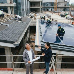

An analysis by the National Renewable Energy Laboratory (NREL) measured that photovoltaic installations on new-construction sites required an average of 3.5 worker-hours per kW — roughly 45% less labor than the 6.4 worker-hours per kW recorded on reroofing retrofit sites. The difference is not accidental. When the structural engineer sizes steel joists for PV dead loads from the start, when the electrician installs conduit runs before drywall goes up, and when the roofer sequences membrane laps around flush-mount racking that is already specified on the construction documents, every trade touches the work once instead of twice. That efficiency gap between “solar-ready by design” and “solar-bolted-on-later” is the central argument for integrating photovoltaic systems into the building design process as early as the schematic phase.
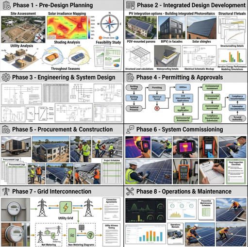
This guide maps the complete workflow — from project kickoff through post-occupancy performance monitoring — for embedding PV into new commercial, institutional, and multi-family residential construction. It is structured around ten sequential phases, each aligned with the decision gates that architects, MEP engineers, general contractors, and building owners already navigate on every project. The phases cover goal-setting, site and building assessment, energy modeling, PV concept design, electrical coordination, structural and roofing integration, regulatory compliance, financial modeling, procurement and commissioning, operations and maintenance, and stakeholder governance.
Three terms recur throughout and are worth defining at the outset. Building-integrated photovoltaics (BIPV) refers to PV products that serve simultaneously as building envelope components — roof tiles, facade glazing, spandrel panels — replacing conventional materials. Building-applied photovoltaics (BAPV) refers to conventional racked PV modules mounted on top of an existing roof or wall surface. Balance of system (BOS) encompasses every component beyond the modules themselves: inverters, racking, wiring, combiner boxes, monitoring hardware, and disconnects. The stakeholders who share responsibility across this workflow typically include the owner or developer, the architect of record, the structural engineer, the MEP/electrical engineer, the facade or roofing consultant, the general contractor, the PV subcontractor, and the local authority having jurisdiction (AHJ).
Project Kickoff and Alignment
Define Objectives and Performance Targets
Before any panel datasheet is opened, the project team must establish measurable PV objectives that align with the building’s broader energy and sustainability goals. Those objectives fall into three categories: energy targets (e.g., offset 40% of annual building electricity consumption, or generate ≥15 kWh/m² of roof area per year), certification targets (e.g., earn LEED v4.1 EA Credit for On-Site Renewable Energy, or meet the Net Zero Energy Building standard under ASHRAE 228P), and financial targets (e.g., achieve a simple payback under 7 years, or maintain a positive NPV at a 6% discount rate over 25 years). Document these in the owner’s project requirements (OPR) — the same document that drives the commissioning authority’s scope — so they carry contractual weight through every design phase.
Identify Stakeholders and Governance
A RACI matrix (Responsible, Accountable, Consulted, Informed) should be drafted at kickoff and updated at each design gate. The table below illustrates a representative assignment for the ten workflow phases covered in this guide:
| フェーズ | オーナー | Architect | Structural Eng. | MEP/Elec. Eng. | PV Subcontractor | GC |
|---|---|---|---|---|---|---|
| Kickoff & Targets | A | R | C | C | C | I |
| Site & Building Assessment | I | R | C | R | C | I |
| Energy Model & PV Sizing | I | C | I | R | C | I |
| PV Concept Design | A | R | C | R | R | C |
| 電気的統合 | I | I | C | R | R | C |
| Structural & Roofing | I | C | R | C | R | R |
| Regulatory & Permitting | A | C | C | R | R | R |
| Financial Modeling | A | I | I | C | C | C |
| Procurement & Commissioning | I | I | I | C | R | A |
| O&M & Monitoring | A | I | I | C | R | I |
| R = Responsible, A = Accountable, C = Consulted, I = Informed | ||||||
Establish Project Timelines and Deliverables
PV-specific deliverables must map onto the building’s standard design milestones — schematic design (SD), design development (DD), construction documents (CD), and construction administration (CA). At SD, the team delivers a PV feasibility memo including estimated capacity, orientation options, and preliminary financial pro-forma. At DD, the deliverables expand to include module selection, inverter sizing, single-line electrical diagram, and a structural load letter confirming roof adequacy. At CD, final construction drawings, specifications (CSI Division 26 and Division 48), interconnection application, and building-permit package are issued. Aligning these PV deliverables with the architectural milestone schedule prevents the all-too-common scenario of the PV design lagging three weeks behind the structural package, delaying both the permit submittal and the steel fabrication order.
Site and Building Assessment
Evaluate Solar Access, Shading, and Orientation
For rooftop PV on new construction, the architect and energy consultant should generate a solar-access study during schematic design — before the roof geometry is locked. Tools such as PVsyst, Helioscope, or Ladybug/Honeybee for Grasshopper can produce annual irradiance maps showing kWh/m² received on every roof surface. A flat roof at 40°N latitude oriented due south and tilted at latitude angle receives approximately 1,400–1,700 kWh/m² of annual global horizontal irradiance (GHI), depending on local climate. Even on a flat roof with zero tilt, low-tilt racking at 5–10° captures 95–98% of the maximum possible irradiation while dramatically reducing wind uplift loads and inter-row spacing requirements.
Assess Roof and Facade Conditions for PV Mounting
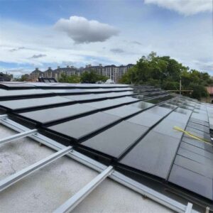
New construction offers the rare opportunity to design the roof specifically for PV — selecting membrane type, insulation thickness, parapet height, and drain placement to maximize usable array area. A TPO or PVC single-ply membrane is the most PV-friendly roofing substrate because it accommodates both ballasted and mechanically attached racking without voiding the roof warranty, provided the racking manufacturer and membrane manufacturer have a written co-warranty or compatibility letter. Standing-seam metal roofs accept clamp-on rail systems with zero roof penetrations — a significant advantage for warranty preservation. For projects considering solar roof tiles as an alternative to conventional panels, the structural substrate, tile interlocking details, and flashing sequences need to be specified at the DD phase.
Perform Shading/Constraint Analysis and Climate Considerations
Even on a new-build site with no existing adjacent structures, self-shading from the building’s own mechanical penthouses, elevator overruns, parapets, and rooftop HVAC equipment can eliminate 10–25% of the available roof area. Run a 3D shadow simulation for the winter solstice at 9:00 a.m. and 3:00 p.m. solar time — the two worst-case shading hours for a symmetric array — and exclude any roof zone where more than 15% of annual irradiance is lost to obstruction shadows. Climate-specific considerations also apply: in heavy-snow regions, steeper tilt angles (≥15°) promote snow shedding and prevent panel burial; in high-wind zones (ASCE 7 basic wind speed ≥150 mph), ballasted systems may require supplemental mechanical attachments or a shift to flush-mount racking to stay within the roof’s structural reserve.

Energy Model and Performance Objectives
Set Energy Goals and PV Sizing Envelopes
The whole-building energy model (typically built in EnergyPlus, eQUEST, or IES-VE) produces the annual electricity consumption baseline against which the PV system is sized. For a typical 50,000 ft² (4,600 m²) Class A office building in a temperate climate, the energy model might project 750,000 kWh/year of total electricity consumption. A 40% offset target would require approximately 300,000 kWh/year from PV. At a site-specific yield of 1,350 kWh/kWp/year (a reasonable assumption for a rooftop at 35°N with mild soiling), the required system capacity is roughly 222 kWp — translating to approximately 1,100 m² of module area using standard 200 Wp/m² panels, or about 24% of the total roof area on a building with a 4,600 m² footprint.
Integrate with Other Onsite Generation/Storage Concepts
If the project scope includes battery energy storage (BESS), the energy model should simulate PV-plus-storage operation to quantify demand-charge reduction, time-of-use arbitrage, and backup-power duration. Coupling a 222 kWp PV array with a 100 kWh / 50 kW lithium-iron-phosphate battery system — the type available through suppliers like Jia Mao Bipv’s energy storage range — can reduce commercial demand charges by 15–30% in markets with strong peak-to-off-peak price differentials. The battery sizing must be integrated into the PV electrical design (shared inverter bus or dedicated hybrid inverter), the structural design (floor-load rating for battery cabinets), and the fire-safety design (NFPA 855 compliance for BESS installations).
Align with Building Code Energy Targets and LEED/Green Programs
Many jurisdictions now embed solar-ready or solar-mandatory provisions in their energy codes. The 2021 International Energy Conservation Code (IECC), adopted or adapted by the majority of U.S. states, includes a solar-ready zone requirement for commercial buildings. California’s Title 24 Part 6 (2025 edition) mandates PV on most new non-residential buildings. Internationally, the EU’s Energy Performance of Buildings Directive (EPBD) recast requires all new buildings to be “zero-emission” by 2030, effectively mandating on-site generation. For LEED v4.1, on-site renewable energy generation earns up to 5 Optimize Energy Performance points (EA Prerequisite and Credit) and additional Innovation credits for projects exceeding 100% offset. Documenting these code and certification requirements at the energy-modeling phase ensures the PV system is sized correctly from the start, rather than being expanded or reduced through change orders during construction.
PV Concept Design and System Sizing
Determine PV Technology, Modules, and Inverters
Module selection for new-construction rooftop projects is driven by four variables: efficiency (Wp/m²), degradation rate (%/year), warranty duration, and compatibility with the chosen racking system. As of early 2025, monocrystalline PERC modules in the 400–600 Wp range dominate commercial rooftop applications, with cell efficiencies of 21–23% and linear degradation warranties guaranteeing ≥84.8% output at year 25 (i.e., 0.55%/year). For BIPV roof applications — where the module replaces the roofing material rather than sitting on top of it — products such as Jia Mao Bipv’s integrated roof modules combine tempered low-iron glass with monocrystalline cells exceeding 22% efficiency and carry 25-year performance guarantees backed by the same factory that manufactures the glass laminate, eliminating the finger-pointing between separate PV and roofing vendors.
Inverter topology choices include string inverters (10–100 kW per unit, lowest cost per watt, best for uniform arrays), microinverters (200–400 W per module, maximum per-panel MPPT, best for shading-impacted or multi-orientation arrays), and power optimizers paired with a central string inverter (a middle ground that provides module-level MPPT while retaining the centralized inverter’s higher conversion efficiency). For commercial rooftops above 100 kWp, string inverters with 2–4 independent MPPT inputs are the standard selection because they minimize hardware count and maintenance complexity while accommodating moderate orientation differences between sub-arrays.
| Criterion | Mono PERC (BAPV) | TOPCon / HJT (BAPV) | BIPV Roof Tile | BIPV Glass Laminate |
|---|---|---|---|---|
| Cell Efficiency | 21–23% | 23–26% | 20–22% | 18–22% |
| Module Wp/m² | 195–220 | 210–240 | 150–190 | 100–200 |
| Degradation Rate (%/yr) | 0.50–0.55 | 0.35–0.45 | 0.45–0.55 | 0.45–0.55 |
| Typical Warranty (Product / Power) | 12 yr / 25 yr | 15 yr / 30 yr | 10 yr / 25 yr | 10 yr / 25 yr |
| Replaces Conventional Material? | No | No | Yes (roof tiles) | Yes (glazing/cladding) |
| ベスト・アプリケーション | Flat commercial roof | High-yield rooftop | Pitched residential/commercial | Facade, skylight, canopy |
| Sources: NREL ATB 2024, manufacturer datasheets, IEA-PVPS Task 15. | ||||
Layout Optimization (Racking, Electrical Routes, Roof/Interface)
Array layout optimization in new construction is a coordination exercise between the architect (who controls rooftop HVAC placement, skylight locations, and parapet heights) and the PV designer (who needs contiguous, shade-free zones with clear conduit runs to the electrical room). The single most impactful design decision at this stage is locating rooftop mechanical equipment on the north side of the roof (in northern-hemisphere projects) to preserve the maximum unshaded south-facing area. On flat roofs, east-west-oriented low-tilt mounting systems (5–10° tilt facing alternately east and west) can increase module density by 30–40% compared to south-facing rows because the inter-row shading setback is nearly eliminated, albeit at a 5–8% per-module yield reduction.
Preliminary Electrical Design and Interconnection Points
The preliminary electrical design establishes string configurations, DC home-run routing, inverter locations, and the point of interconnection (POI) with the building’s electrical distribution. For a 222 kWp system using 580 Wp modules at ~50 V Vmp, each string might contain 18 modules in series (producing roughly 900 V at Vmp — safely below the 1,000 V DC limit mandated by NEC 690 for U.S. commercial systems, or below 1,500 V DC if the jurisdiction has adopted the IEC-aligned limit). The POI is typically a dedicated PV breaker on the main distribution panel (MDP) or, for larger systems, a separate PV switchgear section with utility-grade metering. Identify the POI early because it determines the size and location of the AC conduit riser from the inverter room to the MDP — a riser that must be coordinated with the MEP engineer’s chilled-water piping, ductwork, and fire-suppression mains in the same shaft.
Watch: How to Integrate Solar PV into Your New Build Project
Source: YouTube — covers best practices and advantages of integrating solar PV panels into new construction homes and commercial buildings.
Electrical Integration and Building Systems Coordination
Inverter/Transformer Sizing and Electrical Distribution
Inverter sizing follows the DC-to-AC ratio principle. A ratio of 1.10–1.25 (i.e., 10–25% more DC module capacity than the inverter’s AC nameplate) is standard practice for commercial rooftop systems, because it maximizes inverter utilization during non-peak hours while allowing modest clipping during the few hundred peak-sun hours per year. For the 222 kWp example, an inverter bank rated at 180–200 kVA AC provides a DC:AC ratio of 1.11–1.23. If the building’s distribution is 480/277 V three-phase (standard for U.S. commercial), string inverters natively outputting 480 V AC eliminate the need for a step-up transformer. In markets using 400/230 V three-phase (EU, China, most of Asia), the inverter output matches the building bus directly.
Coordination with DAS/MEP and Fire/Life-Safety Requirements
NEC 2023 Article 690.12 requires rapid shutdown of PV systems on buildings: all conductors within the array boundary must be reduced to ≤80 V within 30 seconds of initiating shutdown. This requirement dictates that either module-level power electronics (MLPEs — microinverters or DC optimizers) or string-level rapid-shutdown devices be installed. The rapid-shutdown initiator is typically wired to the building’s fire-alarm control panel (FACP) so that a fire alarm automatically de-energizes the array before firefighters access the roof — a coordination detail that must appear on both the electrical drawings and the fire-alarm riser diagram. In addition, NEC 690.13 requires a PV system disconnecting means at a readily accessible location, and International Fire Code (IFC) Section 605.11 mandates clear access pathways on the roof: a minimum 914 mm (36 in.) wide path from the roof access point to the array, plus 914 mm setbacks from ridges and eaves to provide fire-brigade ventilation zones.
Cable Routing, Conduit Management, and Safety Clearances
In new construction, DC conduit runs from the rooftop array to the inverter room should be embedded in the building’s vertical electrical chase during the rough-in phase — before drywall, fire-stopping, and ceiling grids are installed. Use EMT (electrical metallic tubing) or rigid metal conduit rated for the local fire-resistance requirement (typically 1-hour or 2-hour rated penetration firestop assemblies at each floor slab). Reserve at least two spare conduit runs (one DC, one communications) for future array expansion or monitoring-system upgrades. Label all PV conduits with permanent markers per NEC 690.31(G) so that future electricians can identify energized solar circuits without opening junction boxes.

Structural and Roofing Considerations
Roof Load Assessment and Structural Verification
A standard ballasted PV racking system on a flat commercial roof adds 1.0–2.5 psf (48–120 Pa) of dead load to the roof structure, depending on ballast density, module weight, and tilt angle. In new construction, this load should be included in the structural engineer’s gravity-load calculations from the start — not added as a retrofit allowance. For comparison, ASCE 7-22 requires a minimum roof live load of 20 psf (958 Pa) for an ordinary flat roof, so a 2.5 psf PV dead load represents roughly 12.5% of the code-minimum live load — significant, but manageable when designed for from the beginning. If the structural system is steel, the engineer sizes open-web steel joists (OWSJ) or wide-flange beams for the combined dead + live + snow + wind + PV load case. If the system is concrete, the additional PV load is rarely a controlling factor, but the point-load concentrations from mechanical attachment clips may require local reinforcement of the concrete deck.
Wind, Snow, and Live-Load Considerations for PV
Wind uplift on rooftop PV is governed by ASCE 7 Chapter 29 (wind loads on building appurtenances and rooftop structures) and SEAOC PV2-2017 (a widely referenced industry guideline for solar PV array wind design). Key variables include building height, terrain exposure category (B, C, or D), roof zone (interior, edge, or corner — with corner zones experiencing 2–3× the uplift of interior zones), and the array’s effective tilt angle. In high-wind zones, the structural engineer may specify supplemental mechanical attachments (through the membrane into the structural deck) at array perimeter modules. Designing these attachment points into the roof framing during new construction — with blocking or reinforcing plates at predetermined grid spacing — is 60–70% cheaper than retrofitting them after the roof membrane is installed.
Roofing Warranty Implications and Warranty-Driven Choices
Roof membrane manufacturers typically require that PV racking be installed by, or in coordination with, a certified roofing contractor, and that the rack manufacturer hold a letter of compatibility or co-warranty with the membrane manufacturer. In new construction, specifying a single roofing-plus-PV scope of work — or at minimum a tri-party warranty involving the roof membrane manufacturer, the racking manufacturer, and the installing contractor — eliminates the warranty gap that plagues retrofit installations. For BIPV roof products that replace the conventional membrane entirely, the warranty structure is simpler: the BIPV manufacturer warrants both the weatherproofing and the electrical performance of the integrated assembly. Jia Mao Bipv’s architectural design guidance addresses these warranty coordination points for both BIPV tile and BIPV glass-laminate roof systems.
Regulatory, Codes, and Permitting Strategy
Utility Interconnection Requirements and Net Metering
The utility interconnection application should be filed as early as the DD phase — not after construction is complete. Most U.S. utilities process solar interconnection under IEEE 1547-2018 (Standard for Interconnection and Interoperability of Distributed Energy Resources with Associated Electric Power Systems Interfaces) and the local tariff’s net-metering or successor program rules. For systems ≤25 kW, the process is typically a Level 1 “simplified” review completed in 10–15 business days. For larger commercial systems (25 kW–5 MW), a Level 2 or Level 3 study may be required, with review periods of 30–90 days and potential requirements for system-impact studies or distribution-grid upgrades that the developer must fund. Filing early protects the project from interconnection-queue delays that have lengthened significantly since 2022 across many U.S. regions, as documented by the EPA’s solar interconnection policy resource.
Building Codes, Fire Brigade Access, and Safety Standards
In the United States, PV installations must comply with NEC Article 690 (Solar Photovoltaic Systems), NEC Article 705 (Interconnected Electric Power Production Sources), IFC Section 605.11 (rooftop access and ventilation pathways), and the applicable edition of the IBC/IRC adopted by the jurisdiction. NEC 2023 introduced clearer terminology for PV source circuits, output circuits, and inverter input/output circuits, and tightened labeling requirements. Fire-access pathways on the roof must be maintained as clear zones — 914 mm minimum width — and marked with reflective tape or paint so they are visible to firefighters during nighttime operations. For non-U.S. jurisdictions, the equivalent standards are IEC 62446-1 (grid-connected PV system commissioning and documentation), EN 62548 (PV array design requirements), and local fire codes that may impose additional separation distances between the array and roof edges.
Local Incentives, Design-for-Constructibility Requirements
Many municipalities offer expedited permitting or reduced fees for solar installations on new construction. The SolSmart designation program, administered by the International City/County Management Association (ICMA), recognizes communities that have streamlined their solar permitting processes — project teams can check their jurisdiction’s SolSmart status to anticipate permit timelines. Additionally, some states mandate “design-for-constructibility” reviews for PV on occupied buildings, requiring the designer to document how the array will be maintained (cleaning access, module replacement procedures) and eventually decommissioned without damaging the roof or facade.
Financial Modeling and Value Proposition
Life-Cycle Cost Analysis and Return on Investment
The financial case for PV in new construction is stronger than for retrofit, because the incremental cost is lower (structural and electrical infrastructure is designed for PV from the start, eliminating rework premiums) and the system lifetime is longer (the roof and PV system age together, avoiding the costly roof-replacement-under-an-existing-array problem). NREL’s Q1 2024 cost benchmark for commercial rooftop PV in the United States was approximately $1.78/Wdc — a figure that drops further in new construction because the racking installation is concurrent with the roof installation, saving an estimated $0.10–$0.20/Wdc in labor overlap.
The bar chart below compares installed cost and 25-year levelized cost of energy (LCOE) for new-construction versus retrofit commercial PV installations:
Chart 1 — Installed Cost and LCOE: New Construction vs. Retrofit Commercial Rooftop PV
Installed Cost ($/Wdc)
New Construction
Retrofit
25-Year LCOE ($/kWh)
New Construction
Retrofit
Assumptions: 222 kWp commercial rooftop, 35°N latitude, 1,350 kWh/kWp/yr yield, 0.5%/yr degradation, 6% discount rate, 30% ITC applied. LCOE calculated over 25-year module warranty period. Source: Adapted from NREL Q1 2024 benchmark and DOE Solar Industry Update Fall 2024.
Financing, Incentives, and Risk Assessment
The three primary financing structures for commercial PV are direct purchase (owner pays upfront, captures ITC and depreciation), Power Purchase Agreement (PPA — a third-party investor owns the system, sells electricity to the building at a negotiated $/kWh rate), and operating lease. For new construction, direct purchase is often preferred because the owner already has construction financing in place and can bundle PV capital into the overall project loan at a lower interest rate than standalone solar financing. The U.S. Federal ITC at 30% (extended through 2032 under the Inflation Reduction Act, with bonus adders for domestic content and energy communities) reduces the effective cost of a $1.58/Wdc new-construction system to approximately $1.11/Wdc after tax credit. State-level incentives vary; DSIRE (Database of State Incentives for Renewables & Efficiency) is the definitive reference for U.S. programs.
Project Cash-Flow Planning and Sensitivity Analysis
Build a 25-year discounted cash-flow model with annual rows for electricity revenue (either avoided utility cost or PPA income), O&M cost (typically $10–$15/kW/year for commercial rooftop, covering inverter maintenance, monitoring, cleaning, and insurance), inverter replacement cost (budget one replacement at year 12–15 at approximately $0.10/Wdc), degradation-adjusted output, and escalation rates for electricity prices (historically 2–3% annually in the U.S.). Run sensitivity scenarios for ±20% on electricity price escalation, ±10% on system yield, and a 1-year delay in interconnection to bound the range of financial outcomes. The pie chart below shows a typical 25-year cost breakdown for a new-construction commercial PV system:
Procurement, Construction, and Commissioning Planning
Procurement Strategy for PV Hardware and Balance-of-System
Issue the PV module purchase order no later than the 50% CD milestone. Standard catalog modules (mono PERC, standard frame sizes) carry lead times of 6–10 weeks from major manufacturers. Custom BIPV products — non-standard dimensions, colored glass, or specific transparency levels — require 12–24 weeks. Lock inverter specifications and order within two weeks of module-order confirmation, because the inverter’s MPPT voltage window must match the actual string Vmp range of the selected modules across the site’s operating temperature extremes. Racking, combiner boxes, and wiring should be ordered at the same time as inverters to ensure all components arrive on-site simultaneously, preventing the all-too-common scene of a pallet of panels sitting on a roof deck for six weeks waiting for rail clamps that were backordered.
For projects requiring mounting brackets and racking hardware alongside the PV modules, procuring from a single supplier that manufactures both the modules and the structural mounting system — as Jia Mao Bipv does with its integrated product lines spanning modules, inverters, brackets, and monitoring accessories — eliminates compatibility risk and consolidates the procurement timeline into one coordinated delivery schedule.
Construction Sequencing and Site Coordination
The PV installation sequence on a new-construction project typically fits within the building’s exterior-envelope phase. The recommended order is: (1) complete roof membrane/weatherproofing, (2) install PV conduit penetrations and firestop assemblies, (3) set racking/rail system, (4) install DC wiring in concealed raceways, (5) place modules on racking, (6) make module-to-module electrical connections, (7) pull home-run DC cables to inverter location, (8) install inverter and AC disconnect, (9) connect to building electrical panel, (10) perform pre-commissioning electrical tests. If the project uses BIPV roof tiles, steps 1 and 3–5 merge because the BIPV product is the roof membrane. In either case, the GC must coordinate the PV subcontractor’s roof access schedule with the roofer, mechanical contractor (for rooftop HVAC curbs), and sheet-metal contractor (for parapet coping) to prevent territorial conflicts on the roof deck.
Commissioning Tests, Performance Verification, and Handover
Commissioning follows IEC 62446-1 (grid-connected PV system documentation, commissioning, and inspection) and should include the following tests documented in a formal commissioning report: open-circuit voltage (Voc) measurement on every string (must be within ±5% of the expected value), insulation-resistance test on all DC circuits (minimum 1 MΩ per string at 500 V DC test voltage), polarity verification, ground-fault detection, inverter functional test (ramp-up, MPPT tracking, anti-islanding), rapid-shutdown functional test, and a 72-hour performance-ratio (PR) test comparing measured energy output to the expected output based on measured irradiance. The commissioning report, along with as-built drawings, string maps, and equipment manuals, forms the handover package delivered to the building owner or facility manager.

Operations, Maintenance, and Performance Monitoring
O&M Plan Formulation and Schedule
A written O&M plan should be delivered as part of the commissioning handover package. The plan specifies inspection intervals (semi-annual visual inspections of modules, racking, and wiring; annual thermal imaging of all strings; biennial inverter preventive maintenance), cleaning schedule (one to two washes per year using deionized water — or less frequently if self-cleaning coatings are applied), and performance benchmarks against which the monitoring system will flag anomalies. For commercial systems, O&M costs are benchmarked at $10–$15/kW/year (NREL, Lawrence Berkeley National Laboratory data), covering monitoring-platform subscriptions, scheduled inspections, inverter maintenance, and cleaning.
Monitoring, Fault Detection, and Performance Guarantees
String-level or module-level monitoring is now standard practice. Systems using smart monitoring platforms can detect string faults (a sudden drop in Voc or Isc), inverter communication failures, and abnormal degradation patterns by comparing real-time PR (performance ratio) against a weather-adjusted expected value. A well-performing commercial rooftop system should maintain a PR of 78–85% in year one. If the monitored PR drops below 75% for two consecutive reporting periods without an attributable weather or grid event, the O&M provider should dispatch a diagnostic inspection. An NREL analysis of 100,000 PV systems found that proactive monitoring-based fault detection recovered an average of 3–5% of lost annual yield compared to systems relying solely on visual inspections — a significant margin over a 25-year asset life.
Long-Term Asset Management and Retrofit Considerations
At the 10–15 year mark, the first major capital expenditure cycle begins: inverter replacement (typical lifespan 10–15 years), possible re-torquing of racking hardware, and roof-condition assessment. Because the PV and roof systems were co-designed and co-installed in a new-construction workflow, the roof membrane should still be in the early-to-middle phase of its 25–30 year warranty, and partial or full re-roofing under an operating PV array is deferred by 10–15 years compared to a retrofit scenario where PV was installed on a roof already 10 years into its life. At the 25-year mark, the project team should evaluate whether to repower (replace modules with higher-efficiency next-generation panels on the existing racking), extend operations with the original modules (which should still produce ≥80% of rated output), or decommission and recycle through PV recycling programs mandated under the EU WEEE Directive or equivalent local regulations.
Stakeholder Engagement, Risk Management, and Governance
Communication Plan and Design-Review Cadence
PV design reviews should be embedded into the building’s standard design-review schedule — not run as a parallel track. At minimum, conduct a dedicated PV design review at three gates: end of SD (confirming feasibility, capacity target, and preliminary layout), end of DD (confirming module selection, electrical single-line, structural load letter, and interconnection application status), and 90% CD (confirming all specification sections, permit-package completeness, and procurement readiness). Each review should include the owner’s representative, the architect, the MEP engineer, the structural engineer, the PV subcontractor, and the GC — the same stakeholders listed in the RACI matrix above. Meeting minutes and action items should be tracked in the project’s BIM 360 or Procore instance so they are linked to the relevant drawing sheets.
Risk Register, Mitigation Strategies, and Change Management
Maintain a PV-specific risk register from kickoff through substantial completion. The ten highest-probability risks on new-construction PV projects, based on industry survey data and published case studies, are: interconnection queue delays, module supply-chain disruption, utility tariff changes reducing net-metering value, AHJ rejecting the rapid-shutdown design, structural engineer requiring mid-design changes for unexpected soil conditions (affecting column loads and therefore roof capacity), roof-area reduction due to late addition of mechanical equipment, inverter model discontinuation during procurement, fire-code interpretation conflicts between AHJ and the PV designer, construction-phase weather delays affecting outdoor electrical work, and commissioning-test failures requiring panel replacement. Each risk should carry an assigned owner, a probability rating (high/medium/low), an impact rating, and a documented mitigation action.
Post-Occupancy Evaluation and Continuous Improvement
One year after commissioning, conduct a post-occupancy evaluation (POE) comparing actual PV performance (kWh generated, PR, availability) against the design-phase energy model predictions. Document the delta and its causes — weather variance, soiling rates higher than modeled, shading from vegetation growth, or inverter downtime. Feed these findings into the design team’s knowledge base so that the next project benefits from calibrated assumptions. In a survey published by the IEA-PVPS program, projects that conducted formal POEs and updated their modeling templates achieved 5–8% higher year-two performance accuracy compared to projects that did not, reducing financial-model risk for future investments.

Integrating PV into new construction is fundamentally a coordination problem — not a technology problem. The modules, inverters, and racking systems available today are mature, cost-competitive, and backed by 25–30 year warranties. The challenge is embedding PV-specific decisions into a building-delivery workflow that already involves dozens of stakeholders, hundreds of deliverables, and a timeline measured in months rather than years. The ten-phase framework presented in this guide aligns PV design milestones with architectural design gates so that every decision — from energy targets at kickoff to PR monitoring at post-occupancy — is made at the right time by the right team members.
Early integration is the single most important success factor. Projects that introduce PV at the schematic design phase, before the structural steel is ordered and the roof geometry is frozen, consistently achieve lower installed costs (10–15% less than retrofit), higher energy yields (because the roof is optimized for PV rather than PV adapting to the roof), and simpler warranty structures (because the roof and PV systems are co-specified). The financial case reinforces this: at a net installed cost of $1.11/Wdc after the 30% ITC, with a 25-year LCOE of $0.038/kWh, new-construction commercial PV now produces electricity at less than half the average U.S. commercial retail rate — an economic advantage that grows every year as utility rates escalate and the PV system’s marginal cost of electricity remains near zero.
Cross-disciplinary collaboration is the mechanism that turns early integration into real-world results. Use the RACI matrix to assign accountability. Use the risk register to anticipate problems before they become change orders. Use the commissioning protocol to verify performance before handing the keys to the building owner. And use the post-occupancy evaluation to improve the next project. If you are starting a new-build project and evaluating PV integration options, Jia Mao Bipv’s installation and design guide provides additional product-specific guidance for both BIPV and BAPV applications.
Frequently Asked Questions About PV Integration in New Construction
What are the key milestones for PV integration in new construction?
The key milestones align with the building’s standard design phases. At schematic design (SD), the team produces a PV feasibility study with estimated capacity and preliminary financial pro-forma. At design development (DD), module selection, inverter sizing, structural load verification, and interconnection-application filing are completed. At construction documents (CD), final electrical drawings, specifications, and permit packages are issued. During construction, the PV installation follows the roofing and electrical rough-in sequence. Commissioning tests — including open-circuit voltage, insulation resistance, and a 72-hour performance-ratio test — are completed before handover. A post-occupancy evaluation at the one-year mark closes the loop by comparing actual performance to design predictions.
How early should PV be considered in the design process?
PV should be considered from the very first schematic design meeting — before the roof geometry, structural system, and mechanical-equipment layout are finalized. NREL data shows that new-construction PV installations average 3.5 worker-hours per kW compared to 6.4 worker-hours per kW for retrofit projects, a 45% labor savings directly attributable to early integration. Introducing PV at the SD phase allows the structural engineer to include PV dead loads in the initial framing design, the architect to locate mechanical equipment to minimize shading, and the electrical engineer to reserve conduit and panel space for the PV system — avoiding costly redesign and rework in later phases.
What are common barriers to PV integration in new buildings and how can they be mitigated?
The most common barriers are interconnection-queue delays (mitigated by filing the utility application at the DD phase), coordination failures between the PV subcontractor and other trades (mitigated by a single integrated installation sequence signed off by all trade supervisors), roof-area reduction due to late mechanical-equipment additions (mitigated by reserving PV zones on the roof plan from SD), fire-code interpretation conflicts (mitigated by early AHJ pre-application meetings), and module supply-chain disruptions (mitigated by issuing the purchase order at the 50% CD milestone with 12–16 week lead-time buffers). A PV-specific risk register maintained from kickoff captures these and other risks with assigned owners and mitigation actions.
What is the typical cost of commercial rooftop PV on new construction in the United States?
Based on NREL’s Q1 2024 cost benchmark, commercial rooftop PV in the U.S. averages approximately $1.78/Wdc installed as a retrofit. New-construction installations are estimated at $1.58–$1.68/Wdc because structural and electrical infrastructure costs are shared with the building’s base scope. After the 30% Federal Investment Tax Credit (ITC), the effective cost drops to approximately $1.11–$1.18/Wdc. The resulting 25-year levelized cost of energy (LCOE) is $0.035–$0.045/kWh — less than half the average U.S. commercial retail electricity rate of approximately $0.09–$0.12/kWh.
What structural loads does a rooftop PV system add to a building?
A standard ballasted PV racking system on a flat commercial roof adds 1.0–2.5 psf (48–120 Pa) of dead load, depending on ballast density, module weight, and tilt angle. Flush-mount systems on standing-seam metal roofs add only 2.5–3.5 psf. For context, ASCE 7-22 requires a minimum 20 psf roof live load for ordinary flat roofs, so PV dead load represents roughly 5–12.5% of the code-minimum live load. In new construction, these loads are incorporated into the structural engineer’s initial gravity-load analysis, adding negligible cost. In retrofit scenarios, the engineer must verify that existing members have sufficient reserve capacity — which sometimes triggers reinforcement that can add $0.05–$0.15/Wdc to the project cost.
What fire-safety codes apply to rooftop PV installations?
In the United States, rooftop PV must comply with NEC 2023 Article 690.12 (rapid shutdown — all array conductors must be de-energized to ≤80 V within 30 seconds of initiating shutdown), IFC Section 605.11 (fire-brigade access pathways — minimum 914 mm clear width from roof access to array, plus 914 mm setbacks from ridges and eaves), and NFPA 1 Chapter 11 (general rooftop safety requirements). The rapid-shutdown system is typically integrated with the building’s fire-alarm control panel for automatic de-energization during a fire event. Outside the U.S., IEC 62446-1, EN 62548, and local fire codes specify equivalent requirements for PV array safety and firefighter access.
How does PV affect roofing warranties on new construction?
Roof membrane manufacturers typically require that PV racking be installed by or in coordination with a certified roofing contractor, and that the racking manufacturer hold a letter of compatibility or co-warranty with the membrane manufacturer. In new construction, specifying a single roofing-plus-PV scope — or a tri-party warranty involving the membrane manufacturer, racking manufacturer, and installer — eliminates the warranty gap that frequently affects retrofit projects. For BIPV roof products that replace the conventional membrane entirely, the BIPV manufacturer warrants both weatherproofing and electrical performance as a single assembly, simplifying the warranty structure significantly.
What monitoring systems should be specified for a commercial PV installation?
At minimum, commercial PV systems should include string-level monitoring that tracks DC voltage, current, and power for each string circuit, plus inverter-level monitoring that captures AC output, efficiency, and fault codes. Module-level monitoring (via microinverters or DC optimizers) provides the highest granularity but at a 5–10% cost premium. The monitoring platform should calculate real-time performance ratio (PR) and compare it against weather-adjusted expected values, triggering automated alerts when PR deviates by more than a predefined threshold (typically 5–10%). An NREL study of 100,000 PV systems found that proactive monitoring recovered an average of 3–5% of annual yield compared to visual-inspection-only maintenance regimes.
What is the difference between BIPV and BAPV for new construction?
Building-integrated photovoltaics (BIPV) are PV products that serve simultaneously as building envelope components — replacing conventional roofing tiles, facade glazing, or spandrel panels. Building-applied photovoltaics (BAPV) are conventional PV modules mounted on racking systems attached to an existing or separately specified roof or wall surface. In new construction, BIPV offers cost savings by eliminating the underlying conventional material, but requires earlier specification (at SD/DD phase) and longer lead times for custom products. BAPV is more flexible in module selection and simpler in procurement, but adds a separate layer to the roof assembly. Both approaches benefit significantly from new-construction integration — BIPV because it must be designed into the envelope from inception, and BAPV because the structural, electrical, and waterproofing coordination is dramatically simpler when done concurrently with the building’s construction.
What O&M costs should be budgeted for a commercial rooftop PV system?
Industry benchmarks from NREL and Lawrence Berkeley National Laboratory place commercial rooftop PV O&M costs at $10–$15 per kW per year, covering monitoring-platform subscriptions, semi-annual visual inspections, annual thermal-imaging scans, biennial inverter preventive maintenance, one to two cleaning cycles per year, and insurance. Over a 25-year system life, O&M accounts for approximately 16% of the total lifecycle cost. The largest single capital expenditure within the O&M horizon is inverter replacement at year 12–15, budgeted at roughly $0.10/Wdc. Self-cleaning coatings on modules — such as those offered by manufacturers like ジャ・マオ・ビップフ — can reduce cleaning costs by approximately 30% over the system’s lifetime.


-300x300.jpg)