Who This Guide Is For — and Why It Matters Now
If you are a curtain wall or roofing contractor integrating PV into complex envelopes, a photovoltaic EPC or energy service provider, a building material distributor or brand entering the solar glazing market, or an architect or design institute specifying energy-generating facades — this guide was built for your specific challenges.
The solar project failure patterns are consistent across all of these roles: structural assessments that get skipped in the rush to bid, permitting packages that fail because a single-line diagram was missing, interconnection applications that sit in the utility queue for 90 days because the system impact study wasn’t anticipated, and commissioning reports that don’t match the energy model — triggering client disputes months after handover.
This guide covers all ten stages of the solar EPC (Engineering, Procurement, and Construction) process — not as a checklist to scan, but as a decision framework that helps you avoid the specific problems that cost projects time, margin, and client relationships.
What is Solar EPC? EPC stands for Engineering, Procurement, and Construction — the three core functions delivered by a solar project firm or consortium. An EPC contractor takes full responsibility for designing the system, sourcing the components, and building it to specification. On more complex commercial projects, these functions are sometimes split across specialist firms working under an integrated project delivery framework.
Stage 1: Project Initiation and Feasibility Assessment

A thorough feasibility assessment takes 2–5 days and prevents the kind of structural surprises that cost $45,000–$120,000 to resolve during installation.
Why Feasibility Is the Most Important Stage Nobody Spends Enough Time On
Most project cost overruns in commercial solar installation are seeded at the feasibility stage — not during construction. A structural load figure that was eyeballed rather than engineered, a shading analysis done on a satellite image rather than on-site, or a utility tariff assumption that turned out to be the wrong rate class can each undermine the financial model that justified the project in the first place.
Spending 2–5 structured days on feasibility is not a delay. It is the most cost-effective activity in the entire project lifecycle.
Site Evaluation: The Three Questions That Determine Everything
Can the structure support it? For rooftop solar on existing commercial buildings, the dead load of a PV system — typically 12–18 kg/m² for rack-mounted modules — must be analyzed against the roof deck and structural framing capacity. For curtain wall and facade BIPV applications, wind load on vertical panel assemblies and connection point loads require early structural engineering input. Skipping this step is how projects discover mid-installation that a structural upgrade adds $80,000 to a $320,000 project.
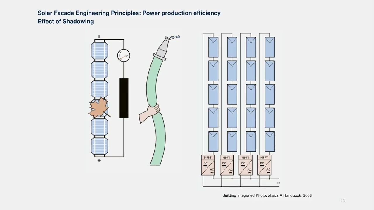
How much shadow falls on the array? Shading analysis using tools like Aurora Solar’s AI-powered engine or physical on-site measurements identifies the specific hours, months, and array zones where trees, parapets, mechanical equipment, or adjacent buildings will reduce output. A shading loss of 15% on a south-facing commercial roof translates directly into 15% fewer kWh generated — and 15% longer payback period. For curtain wall facades, inter-floor shading from projecting slabs requires 3D modeling, not rule-of-thumb assumptions.
Does the energy yield match the financial model? Energy yield modeling — using climate data from NREL’s National Solar Radiation Database or international equivalents — translates irradiance data, panel specifications, and system losses into an annual kWh production forecast. This is the number that drives the ROI calculation. The difference between a P50 estimate (median expected output) and a P90 estimate (output exceeded 90% of years) matters for building owner financial planning.
The ROI Forecasting Conversation EPCs Should Be Leading
Energy service providers and EPC firms that treat ROI forecasting as the client’s responsibility are missing a significant competitive opportunity. Clients — whether they are building owners, developers, or facilities managers — make better decisions faster when the EPC brings a clear post-incentive financial model to the feasibility meeting, not just a system size proposal.
A simple feasibility ROI table for a commercial rooftop project might look like this:
| Parámetro | Valor | Notes |
|---|---|---|
| Gross system cost (installed) | $680,000 | Materials + labor + BOS + design |
| Federal ITC (30%) | −$204,000 | Applied to eligible cost basis |
| State incentive / MACRS depreciation benefit | −$68,000 | Project-specific; verify with tax advisor |
| Net cost to owner after incentives | $408,000 | Effective investment basis |
| Annual energy production (P50) | 380,000 kWh | Based on NREL TMY data for location |
| Annual value at $0.14/kWh blended rate | $53,200 | Escalate at 3%/yr for full model |
| Simple payback (pre-escalation) | 7.7 years | Post-incentive net cost ÷ annual value |
| 25-year cumulative savings | $1.92 million | At 3%/yr utility escalation |
Figures are illustrative. Project-specific tax advice required for ITC application.
Early Stakeholder Coordination: The Architecture-Engineering-Contractor Alignment Meeting
On projects where solar PV is being integrated into a building that is also being designed or renovated — particularly curtain wall BIPV and complex rooftop systems — the most expensive decision the project team can make is to keep the structural engineer, electrical engineer, facade designer, and EPC contractor in separate silos during the design phase.
A single coordinated feasibility meeting — held before any discipline has finalized their scope — is where the decisions that prevent expensive redesigns are made. Integrated project delivery (IPD) frameworks formalize this multi-disciplinary early coordination as a contractual structure, not just a good intention.
Industry Insight: NREL’s analysis of commercial solar project cost drivers found that design change orders after construction mobilization cost an average of 3.2× more to implement than the same change made at the design stage. Early coordination is not a scheduling preference — it is a financial discipline.
Stage 2: Engineering Design — Structural, Electrical, and BIM Integration
BIM-integrated solar design catches conduit conflicts, structural clashes, and electrical routing errors before fabrication begins — when fixes cost a fraction of field corrections.
Structural Engineering: The Non-Negotiable Foundation
Every commercial solar installation — whether rack-mounted on a flat roof, integrated into a curtain wall system, or mounted on a metal standing-seam roofing system — requires structural calculations signed by a licensed structural engineer. The four load categories that must be evaluated for every project are:
Dead load: The static weight of the PV system itself. Rack-mounted modules typically contribute 12–18 kg/m² to the roof’s dead load; BIPV glass panels used in curtain wall applications are generally 20–28 kg/m², comparable to premium laminated safety glass.
Wind uplift: In most U.S. jurisdictions, ASCE 7-22 defines the wind design pressures that racking and mounting systems must resist. Roof-edge and roof-corner zones experience significantly higher uplift forces than field zones — and it is in these zones where under-engineered mounting systems fail. For facade BIPV, wind pressures on vertical surfaces are calculated differently from roof surfaces.
Seismic forces: In Seismic Design Category C, D, E, or F zones, the racking and mounting connections must be evaluated for lateral and vertical seismic forces using IBC/ASCE 7 methods. This is not optional in California, the Pacific Northwest, or significant portions of the Midwest.
Long-term deflection: On long-span roof structures, accumulated deflection under sustained dead load can create drainage issues that trap water against roof membranes and PV system wiring. The structural engineer must evaluate both immediate and long-term (creep) deflection under the combined loading.
Electrical Design: NEC Compliance as a Design Input, Not an Afterthought
The electrical design for a commercial solar system must be developed by or under the direct supervision of a licensed electrical engineer, and it must comply with the applicable edition of the National Electrical Code (NEC) as adopted in the project’s jurisdiction.
String design and inverter selection: The number and configuration of modules wired in series (strings) must be matched to the inverter’s input voltage and current range, accounting for the system’s maximum and minimum operating temperatures. A string voltage that exceeds the inverter’s maximum input voltage at the coldest design temperature is an electrical hazard and an inspection failure.
NEC 690.12 Rapid Shutdown (2023 edition): The 2023 NEC requires that within 30 seconds of rapid shutdown initiation, conductors inside a building are reduced to 30V or less. This effectively mandates Module-Level Power Electronics (MLPE) — microinverters or DC optimizers — on any system where conductors pass through or along a building. According to GreenLancer’s NEC 690.12 guide, this is one of the most common inspection failure points because older designs using string inverters without MLPE do not comply with current code.
IEEE 1547-2018 compliance: For systems connected to the distribution grid, all inverters must comply with IEEE 1547-2018, which sets requirements for voltage, frequency, reactive power, and anti-islanding behavior at the point of interconnection.
BIM Coordination: Finding Conflicts on a Screen, Not on Site
BIM (Building Information Modeling) — a coordinated 3D digital model that integrates structural, architectural, and mechanical/electrical/plumbing (MEP) information — is the most effective tool available for preventing field conflicts on complex solar projects. For curtain wall BIPV, complex roof geometries, or large commercial buildings where the solar system shares space with mechanical equipment, BIM coordination is not a premium service. It is the minimum responsible design standard.
Key elements to model in a coordinated solar BIM include: PV module array layout with exact panel dimensions from the manufacturer’s BIM family, racking or mounting system with all connection points and clearances, conduit routing from array to inverter to switchgear — including all bends, pull boxes, and sleeves through structural members, and inverter and combiner box placements with required maintenance clearances.
Enclos’s analysis of BIM innovation in curtainwall design documents how BIM coordination reduces field conflicts by 40–60% on complex facade projects — a benefit that translates directly into fewer change orders, faster installation, and cleaner final inspections.
For curtain wall contractors and facade contractors specifying BIPV glass products, working with a manufacturer that provides Revit-ready BIM families — including electrical connection point locations, weight data, and performance specifications — dramatically reduces the modeling time required. Jia Mao BIPV’s technical documentation package includes product-specific data compatible with standard BIM workflows, available through their technical support team.
Stage 3: Permitting Strategy and Regulatory Navigation
The Anatomy of a Commercial Solar Permit Package
A complete commercial solar permit package typically includes these documents — and a missing or incomplete document is what creates a re-review cycle that adds 3–8 weeks to the project schedule:
| Document | What It Covers | Common Errors That Trigger Re-Review |
|---|---|---|
| Cover sheet / project summary | System size, address, scope description | System size mismatch between cover sheet and SLD |
| Site plan | Module layout, setback dimensions, access pathways | Missing fire setback dimensions; fire department access path not shown |
| Single-line diagram (SLD) | Complete electrical schematic from modules to grid | Missing rapid shutdown device; incorrect wire sizing notation |
| Structural calculations | Racking attachment loads; deck/frame capacity | Not stamped by licensed structural engineer; missing dead load calculation |
| Module spec sheet | Certified electrical characteristics | Module not on approved equipment list for jurisdiction |
| Inverter spec sheet | Grid interconnection specifications | Missing UL or IEEE 1547 certification documentation |
| Rapid shutdown compliance sheet | MLPE placement, conductor zones | Not referenced to NEC 690.12 (2023) or jurisdiction’s adopted code edition |
| Roof plan / framing plan | Rafter/joist layout, attachment point positions | Attachment points not aligned to framing members in structural plan |
AHJ Navigation: Why Jurisdiction-Specific Knowledge Matters
The Authority Having Jurisdiction (AHJ) — the local building or fire department office responsible for reviewing and approving your permit application — operates under whichever edition of the NEC and IBC their jurisdiction has adopted. As of 2025, U.S. jurisdictions are spread across NEC 2017, 2020, and 2023 editions, with individual states and cities sometimes adopting local amendments.
What this means practically: a permit package that passes first review in Los Angeles (NEC 2020, California Title 24) may require significant revision for Chicago (NEC 2023 with Illinois amendments) or Houston (NEC 2020, NFPA 1 local fire code). Maintaining a jurisdiction compliance matrix — a spreadsheet that tracks the NEC edition, fire code, structural code, and key local amendments for every AHJ where you regularly pull permits — is a discipline that high-performing EPC firms treat as a core operational asset.
Pre-Validation: Reducing Review Cycles Through AHJ Pre-Application Meetings
Many AHJs offer pre-application meetings where the EPC or permit expeditor can walk through a draft permit package with the plan check engineer before formal submission. These meetings cost 1–2 hours of staff time and routinely eliminate 2–3 rounds of re-review. For large commercial projects or projects in jurisdictions with complex local requirements, pre-application meetings are not optional — they are the professional standard.
Stage 4: Procurement — Supply Chain Optimization and Material Sourcing
Why Procurement Strategy Is an EPC Core Competency
In 2025, the solar supply chain presents a specific challenge: module prices have compressed significantly due to Chinese manufacturing overcapacity (JinkoSolar’s Q3 2025 gross margin of 7.3% is the downstream signal), but tariff exposure, logistics lead times, and quality consistency have become more variable. An EPC firm that treats procurement as a transactional activity — issuing an RFQ, picking the lowest bid, and hoping the materials arrive — is operating without a margin of safety in a supply environment that has none to spare.
Strategic procurement means qualifying suppliers before projects are awarded, not after. It means understanding the factory-to-jobsite lead time for every major component in advance, building contractual lead time commitments into supplier agreements, and identifying qualified substitutions for every critical component before the project schedule makes substitution a crisis rather than a contingency.
Component Lead Times: What to Plan For in 2025
The following lead times represent typical 2025 market conditions for commercial solar projects in the U.S. market:
| Component | Typical Lead Time | Risk Level | Mitigation Strategy |
|---|---|---|---|
| Standard monocrystalline modules | 4–8 weeks | Moderado | Pre-order once permit is submitted |
| Premium BIPV glass panels (custom dimensions) | 8–14 weeks | Alta | Confirm dimensions at permit stage; place order immediately |
| String inverters (commercial, 30–100 kW) | 6–10 weeks | Moderado | Pre-qualify two approved alternatives |
| Central inverters (>250 kW) | 10–16 weeks | Alta | Early LOI to manufacturer; include in permit docs |
| DC optimizers / microinverters | 4–8 weeks | Low–Moderate | Standard stock item for most distributors |
| Racking systems (ballasted, standard) | 3–5 weeks | Bajo | Order after permit approval |
| Custom racking (non-standard geometries) | 6–12 weeks | Alta | Design-phase coordination required |
| Transformers / switchgear | 12–20 weeks | Very High | Order at contract execution, not permit approval |
Sources: Energyscape Renewables supply chain analysis 2025; EPC firm procurement data.
Quality Assurance in Procurement: The Factory Audit Framework
For BIPV glass and specialty solar products — where product performance must meet both PV electrical standards and building envelope structural standards — procurement QA cannot be limited to reviewing a specification sheet. The key QA protocols for a professional procurement function include:
Electroluminescence (EL) imaging on a statistical sample (typically 5–10%) of produced BIPV modules before shipment, to identify cell cracks, delamination, or hotspot-prone zones that are invisible to visual inspection but will degrade performance within 2–5 years.
Certification verification — not just asking for the certificate, but verifying the certificate number against the issuing body’s live database. IEC 61215, IEC 61730, and UL 1703 certifications can be verified through the certification body’s online registry.
Factory hold-point inspection by a third-party inspector for orders exceeding $150,000 in value. Unicorn SD’s factory audit checklist framework documents the key inspection points for solar module production, covering QMS documentation, raw material traceability, and production process consistency.
Building material distributor’s role: Distributors who supply both BIPV glass products and conventional building materials to EPC contractors have a significant opportunity to add value at the procurement stage — by bundling products (BIPV glass with compatible framing systems or roofing membranes), providing pre-verified technical documentation, and offering consistent lead time commitments backed by stocked inventory. For Jia Mao BIPV’s product range, distributors can obtain product certification documentation and technical data packages appropriate for commercial permit submissions directly from the manufacturer’s technical team.
Stage 5: Interconnection and Utility Coordination

Utility interconnection timelines for commercial solar range from 30 days to 12+ months. The difference is almost entirely determined by preparation quality and proactive utility relationship management.
The Interconnection Process: What Actually Happens and How Long It Takes
Utility interconnection is the approval process through which a solar system gains permission to connect to and export power to the distribution grid. For commercial solar projects — systems above roughly 10 kW in most utility territories — the process involves formal applications, utility engineering review, and in many cases technical studies that can significantly extend the project timeline.
The typical commercial interconnection process runs through these stages:
Pre-application screening: Many utilities offer a pre-application meeting or online screening tool to assess whether the proposed system size and point-of-interconnection will likely require an additional study (feasibility or system impact study). For projects smaller than the “screens” defined in the utility’s interconnection tariff, approval can often proceed without a full study.
Application submission: The formal application package typically includes single-line diagrams, equipment specifications (inverter, modules, transformer if applicable), site plans, and the interconnection agreement. As documented by EA Global’s interconnection guide, completeness of the initial submission is the single most controllable variable in application timeline — an incomplete application is returned for correction, resetting the review clock.
Feasibility study: Required when the proposed system exceeds a utility-defined threshold for the specific distribution circuit. Typically takes 30–60 days and evaluates whether the system can connect without infrastructure upgrades.
System impact study: Required when the feasibility study identifies potential issues. More detailed analysis of voltage, thermal loading, and protection coordination impacts. Can take 60–180 days depending on utility workload.
Permission to Operate (PTO): Once physical installation is complete, the utility performs a final inspection and issues the PTO — the authorization to operate the system in parallel with the grid. Commercial battery-paired systems average 8–12 weeks from application to PTO for streamlined applications; complex projects with study requirements can run 6–12+ months.
Strategies for Reducing Interconnection Soft Costs
The “soft costs” of solar projects — permitting, interconnection, customer acquisition, and project management overhead — represent approximately 35–40% of total commercial project cost in the U.S., according to NREL’s solar benchmarking data. Interconnection alone accounts for 8–15% of soft costs on projects that require studies. The practical strategies that reduce these costs:
Submit the interconnection application concurrent with or immediately after permit submission — not after installation. Interconnection review and building permit review can run in parallel, compressing the overall project timeline.
Develop a standing relationship with the interconnection engineer at your primary utility territories. Understanding a utility’s specific review criteria, their preferred SLD format, and the typical study trigger thresholds for specific circuits reduces the uncertainty that drives conservative (expensive) project design choices.
Size the system below study thresholds where financially viable. In many utility territories, a system at 499 kW may qualify for expedited review while a 501 kW system triggers a system impact study adding 90–120 days. The financial value of that timeline compression often exceeds the generation value of the additional 2 kW.
Stage 6: Construction Execution and Field Supervision
Phased Installation Planning for Roofing and Curtain Wall Integration
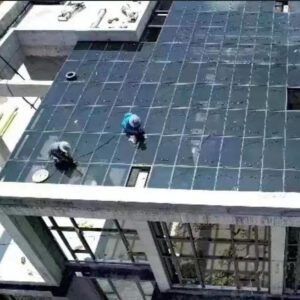
Solar installation on buildings that are simultaneously undergoing roofing or curtain wall work requires sequence planning that most standalone solar contractors are not trained for — and that most roofing or curtain wall contractors are not experienced in managing on the electrical side. The most effective execution model brings both trades under a coordinated installation plan developed before mobilization, not improvised on site.
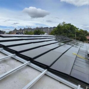
For metal roofing integration, the key sequence issue is that the roofing membrane or standing seam system must be complete and weathertight before solar attachment penetrations are made. Making penetrations through an incomplete roof creates waterproofing risk and forces re-work if the roof sequence changes. Proper flashing integration with certified mounting systems — using manufacturer-specific flashing kits that maintain the roofing system’s warranty — is the technical standard that prevents the leak-callbacks that erode contractor reputation and margin.
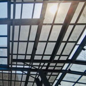
For curtain wall BIPV integration, electrical conduit routing, junction box placement, and string wiring must be coordinated with the curtain wall installation sequence because the cavity behind the panels — where wiring lives — becomes inaccessible once panels are installed. Conduit that was supposed to run through a mullion cannot be rerouted after the unitized panel system is in place. This is where BIM coordination from Stage 2 pays its most direct dividend.
On-Site QA/QC Protocols
Quality control on a solar installation is not a documentation exercise. It is a physical inspection discipline that prevents the failures — loose grounding connections, unlabeled conductors, rapid shutdown devices not connected — that cause inspection failures and, more seriously, safety events.
A minimum QA/QC protocol for commercial solar construction includes:
Daily installation records: Crew, modules installed, string connections completed, conduit installed. These records serve as the evidence base for the as-built drawings and are critical for warranty administration.
Torque documentation: All module-to-racking and racking-to-roof attachment bolts must be torqued to manufacturer specification and documented with calibrated torque wrenches. Un-torqued connections are the primary cause of mounting system failures under wind load.
Grounding continuity checks: Every module frame in the array must have a verified grounding path to the grounding electrode system. A single break in grounding continuity creates a shock hazard and an NEC violation. FTQA360’s QAQC framework for large solar projects documents the digital punch list approach that enables systematic tracking of installation quality across multiple subcontractors.
String open-circuit voltage verification: Before connecting strings to the inverter or combiner box, measure the open-circuit voltage of each string and compare to the calculated expected value. A string Voc that is significantly lower than expected indicates a module issue, a wiring error, or a connection problem — all far cheaper to fix before the inverter is connected than after.
Stage 7: Inspection Readiness and Code Compliance
The Four Most Common Commercial Solar Inspection Failures — and How to Prevent Them
Commercial solar inspections by building and electrical departments fail for predictable reasons. The EPC firms and contractors with the highest first-time pass rates are not more technically talented than those with multiple re-inspection cycles — they are more systematic about pre-inspection compliance validation. The four issues that trigger failures most consistently:
1. Grounding and bonding errors. NEC Article 690.43 requires that all module frames, racking components, and metallic enclosures be bonded. The most common failure is a bonding connection that uses an incompatible bonding method — for example, a self-tapping screw into an aluminum rail that does not make the required metal-to-metal contact specified in the UL listing of the bonding hardware. Verify each bonding connection method against the hardware manufacturer’s UL listing before inspection.
2. Rapid shutdown non-compliance. Under NEC 690.12 (2023 or 2020 depending on adopted edition), conductors within a building must be reduced to 30V or less within 30 seconds of rapid shutdown initiation. Systems using string inverters without module-level power electronics frequently fail this requirement. Verify compliance by checking the adopted NEC edition in the jurisdiction and confirming that the installed MLPE devices are listed for rapid shutdown compliance.
3. Labeling deficiencies. NEC 690 requires specific warning labels at multiple points: the AC and DC disconnects, the main service panel, the inverter, and any combiner boxes. Labels must use specific language, meet minimum size requirements, and be made of durable outdoor-rated materials. Missing, incorrect, or hand-written labels on laminated paper are consistent inspection failure points.
4. Fire setback violations. The IBC and most fire codes require clear access pathways on solar-covered roofs for firefighter access — typically 6-foot-wide pathways to each roof section and 18-inch setbacks from ridges, hips, and valleys on sloped roofs. A module layout that was designed for maximum output without validating fire setback compliance can require an array redesign at the inspection stage.
Pre-Inspection Checklist for Commercial Solar Projects
Run through this verification sequence before requesting inspection — not the day before, but during the final week of installation when issues can still be resolved without delaying the inspection:
- All required NEC labels installed at correct locations with correct language and outdoor-rated materials
- Rapid shutdown system tested: confirm conductors de-energize to ≤30V within 30 seconds of initiating shutdown
- Grounding continuity verified end-to-end from the last module frame to the grounding electrode
- Fire setback dimensions measured and compared to site plan — photograph each setback
- All conduit secured at NEC-required intervals; conduit fill does not exceed code limits
- Inverter and combiner box access clearances comply with NEC working space requirements (typically 36″ in front)
- All junction boxes closed and weathertight; no open knockouts
- Permit placard posted at the electrical service entrance or as directed by the AHJ
- Photographic record of each string connection, grounding connection, and attachment point taken before concealment
Stage 8: Commissioning and Performance Validation
Why Commissioning Is Not the Same as Turning the System On
The solar industry has a commissioning problem: many “commissioning” protocols consist of turning on the inverter, verifying that power is flowing, and calling the system operational. This approach misses the diagnostic information that would reveal degraded modules, wiring errors, and performance shortfalls before the system is handed over — when fixing them is still the contractor’s cost rather than a warranty dispute.
A professionally executed commissioning protocol for a commercial solar system includes four core activities:
IV curve tracing. An IV (current-voltage) curve trace measures the electrical characteristics of each string against its expected performance curve under current irradiance conditions. A string with a degraded module, a mismatched module in the string, or a partial shading condition will show a characteristic deviation from the expected curve that identifies the problem. According to Fluke’s IV curve tracing guidance, IV curve tracing during commissioning is the single most effective method for verifying installation quality before handover — because it tests actual electrical performance, not just connectivity.
Insulation resistance testing. Measures the resistance between the DC conductors and ground. A low insulation resistance reading indicates compromised wiring insulation — a potential ground fault that is a safety hazard and an NEC violation. This test must be performed with all modules connected and the system energized to its operating voltage.
Functional testing of protection systems. Verify that the rapid shutdown system responds correctly to an initiation signal, that all disconnect switches operate smoothly, and that the inverter’s anti-islanding protection responds correctly to a simulated grid outage.
Performance verification against modeled output. Compare the system’s measured output under current irradiance (using on-site irradiance measurement) against the PVsyst model’s expected output at the same irradiance. A performance ratio (PR) below 0.78 for a well-designed commercial system at commissioning is a signal that warrants investigation before handover.
Stage 9: Handover, O&M Planning, and Warranty Management
What a Professional Handover Package Contains
The handover package is the document set that transfers operational responsibility for the solar system from the EPC to the building owner and their O&M team. A professional handover package contains everything the O&M team needs to operate, maintain, and troubleshoot the system without calling the EPC for basic information. It typically includes:
As-built drawings: Reflecting actual installation — not the construction drawings. Module layout with serial numbers, string wiring diagram with actual conductor lengths and conduit routing, single-line diagram updated for any field changes, and structural attachment layout.
Equipment documentation: Manufacturer installation manuals, operation manuals, and warranty registration confirmations for every major component.
Commissioning test reports: IV curve traces, insulation resistance measurements, functional test results, and initial performance ratio.
Warranty documentation: Module performance warranty (typically 25-year, ≥80% output), inverter product warranty (typically 10–12 years), racking/mounting system warranty, and workmanship warranty from the installing contractor.
O&M manual: Inspection schedule (recommended annually for electrical, more frequently for mechanical connections in high-wind zones), cleaning protocol, troubleshooting decision tree for common alerts, and emergency contact list for utility, EPC, and key component manufacturers.
Solar Best Practices’ handover-to-O&M chapter documents the industry standard for EPC-to-O&M transition documentation — a useful reference framework for EPCs building their handover template.
Warranty Coordination: Who Owns What When Something Goes Wrong
The most common source of post-installation warranty disputes is ambiguity about who is responsible for a given failure. A proactive warranty coordination structure addresses this before handover:
| Failure Type | Responsible Party | Documentation Required |
|---|---|---|
| Module power below warranted output | Module manufacturer | IV curve trace, irradiance measurement, temperature log |
| Module delamination or physical defect | Module manufacturer | Photographic evidence, EL imaging |
| Inverter malfunction | Inverter manufacturer | Error code log from monitoring system, fault history report |
| Racking corrosion or attachment failure | Racking manufacturer + installer | Photographic evidence, torque records from installation |
| Roof leak at attachment penetration | Installing contractor | Inspection photos, flashing installation records |
| System underperformance (no specific component failure) | EPC (workmanship warranty) | Performance model comparison, monitoring data, site conditions |
For building material distributors and brands supplying solar products: offering structured warranty backstop support — a defined process for escalating warranty claims from the EPC to the manufacturer, with committed response times — is a differentiated service that justifies premium product pricing and builds long-term distributor-EPC relationships.
Stage 10: Post-Installation Support and Performance Monitoring

Remote monitoring transforms solar system management from reactive break-fix to proactive performance optimization — delivering sustained ROI for building owners and O&M providers.
Remote Monitoring: The Shift from Break-Fix to Predictive Management
A commercial solar system without remote monitoring is like a building HVAC system without a BMS — you only discover problems when they are already expensive. A system that has been underperforming by 12% for three months due to a failed optimizer or a string connection issue has lost the owner 3+ months of expected energy savings before anyone noticed.
Modern remote monitoring platforms provide string-level performance data updated every 5–15 minutes, automatic alerts when string output deviates from modeled performance by a user-defined threshold, generation versus model comparison dashboards that separate weather-driven underperformance from system-driven underperformance, and inverter fault code logging with remote diagnostics access for the service team.
For EPC firms offering O&M services as a revenue stream: remote monitoring platforms including SCADA-based commercial platforms (SMA Sunny Portal, SolarEdge monitoring, Enphase Enlighten, and third-party SCADA systems compliant with IEC 61724) provide the data infrastructure that makes proactive O&M economically viable. Rather than dispatching a technician based on a client call, the O&M team dispatches based on monitoring data that identifies the specific string and component causing the underperformance — reducing service dispatch time and cost per event.
Predictive Maintenance: Four Warning Signs That Appear in Monitoring Data Before Failures Occur
String output decline trend (gradual, 0.5–2% per month): Indicates a developing module defect, cell degradation, or connection corrosion. Intervention before complete failure prevents a single-module issue from becoming a multi-module string failure.
Inverter clipping hours increasing: When the inverter’s output is capped by its maximum power limit more frequently than modeled, it may indicate array growth (soiling correction revealing higher output than expected) or more commonly, a system configuration issue that reduces utilization.
Temperature-correlated performance anomaly: A string that shows normal output in cool morning conditions but significant underperformance in peak afternoon heat has a temperature coefficient issue — either a module with elevated temperature sensitivity or a hotspot-prone cell cluster. IV curve tracing at elevated temperatures will confirm.
Communication dropout pattern: An optimizer or microinverter that shows intermittent communication dropouts before going offline is typically experiencing a loose or corroding connection. Catching this before it becomes a complete hardware failure avoids a replacement cost that is 3–5× higher than a connection correction.
Performance Reporting for Clients and Investors
Building owners with ESG reporting obligations and investors with energy performance requirements need reporting that goes beyond “the system is working.” Professional O&M reporting for commercial solar includes monthly production reports comparing actual generation to P50 model, annual performance ratio trend analysis, cumulative carbon reduction documentation (using the appropriate regional emissions factor), and utility bill verification showing the correlation between solar generation and bill reduction.
For EPCs and energy service providers offering performance contracting — where the EPC guarantees a minimum energy output and compensates the owner if the system underperforms — this reporting infrastructure is the operational foundation of the guarantee. The P50 and P90 performance estimates established at the feasibility stage (Stage 1) become the benchmark against which actual performance is measured annually. As Aurora Solar’s production guarantee guide documents, realistic EPC performance guarantees typically warrant 90% of modeled production at Year 10 and 80% at Year 25.
Watch: BIPV Structural and Electrical Engineering Principles in Practice
▶ Click to watch: An engineering-focused overview of structural safety, electrical integration, and BIPV system design principles for curtain wall contractors, EPC firms, and facade consultants.
Digital Tools That High-Performing EPCs Use at Each Stage
The following tools represent the current professional standard for commercial solar project delivery. EPCs and consultants using spreadsheets and generic project management software at stages where specialized tools exist are carrying avoidable risk and administrative overhead.
| Stage | Tool | Primary Function | Who Uses It |
|---|---|---|---|
| Feasibility & Design | HelioScope | Layout optimization, shading analysis, energy modeling | EPCs, design engineers |
| Feasibility & Design | PVsyst | Detailed energy simulation with bifacial, far shading | Design engineers, consultants |
| BIM Coordination | Autodesk Revit + BIM 360 | Coordinated 3D model, clash detection | Architects, facade engineers |
| Permitting | Aurora Solar | Automated permit-ready SLD generation | EPCs, permit expeditors |
| Construction Management | Procore | RFI management, punch lists, document control | GCs, EPC project managers |
| Quality Control | GoFormz / FieldLens | Digital inspection checklists, photo documentation | Field supervisors, QA/QC teams |
| Commissioning | Fluke 1500 series IV tracer | IV curve measurement, string diagnosis | Commissioning engineers |
| Monitoring | SolarEdge / Enphase / SCADA | Real-time performance, fault detection | O&M teams, EPCs |
The Role of BIPV Glass Suppliers in a Professional EPC Process
For EPC firms and contractors integrating BIPV glass into commercial curtain wall and facade projects, the supplier relationship is not a transactional procurement event. It is a technical partnership that spans from design coordination (BIM families, load calculations, energy yield data) through commissioning (performance verification data, EL imaging records) and into O&M (replacement glass availability, performance warranty administration).
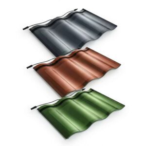
Jia Mao BIPV operates at 3 GW annual production capacity with product certifications covering IEC 63092-1, IEC 61215, IEC 61730, and B1-grade flame retardancy — providing the documentation package that commercial permit submissions and utility interconnection applications require. Their BIPV product range covers transparent, semi-transparent, colored, and specialty glass configurations for curtain wall, skylight, facade, and roof tile applications.
For project-specific technical support — including BIM component files, energy yield simulations, structural load calculations, and certification documentation for permit submissions — the Jia Mao BIPV team provides direct technical engagement at the design stage. Contact details and project inquiry form are available at jmbipvtech.com/contact/.
Glossary of Key Terms
AHJ (Authority Having Jurisdiction): The government agency (typically a local building or fire department) responsible for reviewing and approving construction permit applications and conducting inspections.
BIM (Building Information Modeling): A coordinated 3D digital model integrating structural, architectural, and MEP information, enabling clash detection and as-built documentation.
BIPV (Building-Integrated Photovoltaics): Solar cells integrated directly into building materials — glass, cladding, roofing — that replace conventional building products while generating electricity.
EPC (Engineering, Procurement, and Construction): A project delivery model in which a single contractor or consortium takes full responsibility for all three phases of a solar project.
IV Curve Tracing: An electrical diagnostic test that measures the current-voltage relationship of a solar module or string under current irradiance, used to verify performance and detect defects.
MLPE (Module-Level Power Electronics): DC optimizers or microinverters installed at each solar module to comply with NEC 690.12 rapid shutdown requirements and improve string-level monitoring.
NEC (National Electrical Code): The U.S. standard for electrical installation safety, published by the NFPA and updated every three years. Solar systems are primarily governed by NEC Article 690.
P50 / P90: Statistical estimates of annual energy yield. P50 is the median expected output (50% probability of exceeding); P90 is the more conservative estimate exceeded 90% of years. Used in financial modeling and performance guarantees.
Performance Ratio (PR): The ratio of a solar system’s actual output to its theoretical output under current irradiance conditions. A well-designed commercial system at commissioning typically shows PR of 0.80–0.85.
PTO (Permission to Operate): The utility’s authorization for a solar system to operate in parallel with the grid, issued after interconnection application review and physical inspection.
Rapid Shutdown: NEC 690.12 requirement that solar system conductors inside a building be de-energized to 30V or less within 30 seconds of initiating shutdown — designed to protect firefighters responding to a building fire.
Preguntas frecuentes
FAQ 1: How early should solar be integrated into the building design process?
Ideally during schematic design — the earliest formal design phase when building massing, orientation, and structural system are being determined. For curtain wall BIPV and complex rooftop systems, integration at schematic design allows solar panel placement to inform structural framing decisions, facade zone designations, and electrical rough-in placement before those elements are locked. Attempting to integrate solar after design development is complete typically means either accepting a suboptimal system layout or generating change orders to accommodate electrical routing and structural reinforcement that was not anticipated.
FAQ 2: What structural considerations are critical when mounting solar on roofing or facades?
The four load categories that a licensed structural engineer must evaluate for every solar installation are dead load (the static weight of the PV system), wind uplift (governed by ASCE 7-22 for most U.S. jurisdictions), seismic forces (required in Seismic Design Categories C through F), and long-term deflection (particularly critical on long-span roof structures where accumulated deflection creates drainage issues). For curtain wall BIPV, wind pressure on vertical surfaces is calculated under different coefficients than roof surfaces, and connection point loads on curtain wall framing members require facade-engineering review.
FAQ 3: How do we ensure our solar design meets local permitting requirements across multiple jurisdictions?
Maintain a jurisdiction compliance matrix — a working spreadsheet updated for each AHJ where your firm regularly pulls permits, covering the adopted NEC edition, IBC edition, fire code, and key local amendments. Use standardized, modular design templates pre-validated in common AHJs as the starting point for each project, then apply jurisdiction-specific adjustments documented in the matrix. Invest in pre-application meetings with AHJs on first-time jurisdictions — the time cost is 2–3 hours; the value is typically 3–5 rounds of re-review avoided.
FAQ 4: What are the most common reasons for failed solar inspections?
The four most consistent causes of commercial solar inspection failures are: (1) improper grounding or bonding that does not meet NEC 690.43 using listed bonding hardware, (2) rapid shutdown non-compliance — either MLPE devices not installed or not properly wired for NEC 690.12 compliance, (3) labeling deficiencies — missing labels, incorrect label language, or non-durable label materials, and (4) fire setback violations — module layouts that do not maintain required firefighter access pathways and ridge/valley setbacks. A structured pre-inspection checklist reviewed by the project’s lead electrician 5–7 days before inspection eliminates virtually all of these failures.
FAQ 5: How can general contractors better coordinate with solar EPCs on mixed-use projects?
Establish an Integrated Project Delivery (IPD) structure with shared BIM models from the design phase, contractual language that defines the interface between the solar EPC scope and the GC scope (particularly for roof penetrations, conduit sleeves through structural members, and electrical rough-in), and weekly coordination meetings with defined agenda items covering active installation sequence, upcoming interfaces, and open RFIs. The single most common coordination failure is the solar conduit that needs to pass through a structural member that the GC’s crew has already poured or framed — preventable entirely with a BIM clash detection review before mobilization.
FAQ 6: What documentation is required for utility interconnection approval?
The standard documentation package for commercial utility interconnection applications includes: single-line diagram (SLD) showing the complete system from modules to point of interconnection, equipment list with manufacturer and model for all inverters and key equipment, site plan showing array location relative to the utility meter and service entrance, and interconnection application form with system size and owner information. For systems above the utility’s screen thresholds (varies by utility, typically 200 kW to 2 MW), a feasibility study or system impact study may be required — these are utility-commissioned analyses, not documents the applicant prepares.
FAQ 7: How do we handle material delays without compromising project timelines?
Three parallel strategies: (1) Build a buffer stock of the highest-risk, longest-lead-time components — particularly specialty inverters and custom BIPV glass — secured before project mobilization, not after. (2) Pre-qualify alternate suppliers for every critical component at the project design stage, and confirm that those alternates are code-compliant substitutions before the original component lead time becomes a crisis. (3) Design the system using modular, standard-dimension components where possible — custom-dimensioned modules have lead times 2–3× longer than standard sizes and have no viable substitution path.
FAQ 8: Can solar be integrated into metal roofing or curtain wall systems without leaks?
Yes, reliably — when using certified mounting systems designed specifically for the roofing profile or curtain wall framing system, with manufacturer-specified flashing kits that maintain the roofing system’s waterproofing warranty. The failure mode that creates leaks is not the technology — it is improper flashing installation, sealants applied to dirty or wet surfaces, and mounting hardware torqued incorrectly. Workmanship warranties from the installing contractor (distinct from the product warranty) that specifically cover waterproofing integrity at solar attachment points are the appropriate risk management tool for building owners.
FAQ 9: What role do architects play in ensuring solar compliance with building codes?
Architects are the responsible party for coordinating fire code setback requirements (specifying compliant module-free zones on the roof plan), roof access pathway design for firefighter access, loading information communicated to the structural engineer, and interface between the solar system and the building envelope for waterproofing, fire-stopping, and aesthetic compliance. For BIPV facade applications, architects must also coordinate the integration of solar panels with the fire-rated wall assembly — NFPA 285 testing must be performed on the complete assembly, not just the panel in isolation.
FAQ 10: How do EPCs manage quality control across multiple subcontractors?
Standardized QA/QC through three mechanisms: (1) Pre-construction kickoff meetings where the subcontractor quality requirements are documented and signed off before work begins, (2) Standardized field inspection checklists using digital tools (GoFormz, Procore quality management) that capture photographic evidence for each required inspection point — grounding connections, torque verification, string polarity checks, and conduit fill — with GPS-timestamped documentation, and (3) Third-party QA audits by an independent inspector on projects above $500,000 in value, providing an objective verification layer that protects the EPC from subcontractor quality failures that would otherwise become the EPC’s warranty liability.
FAQ 11: What are the NEC 2023 requirements for rapid shutdown in commercial solar?
NEC 2023 Section 690.12 requires that within 30 seconds of rapid shutdown system initiation, conductors within the boundary of the building (including those in conduit along or inside the building) are reduced to 30V or less. This effectively mandates MLPE — module-level power electronics (DC optimizers or microinverters) — for most commercial building-mounted systems. The rapid shutdown initiation device must be located at a readily accessible location outside the building, typically adjacent to the utility meter, and must be clearly labeled. Some utility-scale ground-mount systems are exempt from the building-interior conductor requirements, but building-mounted commercial systems must comply fully.
FAQ 12: How can building material distributors add value in solar projects?
By moving from transactional product supply to solution bundling: offering BIPV glass products combined with compatible framing systems, roofing membranes, or flashings as an integrated package; providing pre-verified technical documentation (certification sheets, load calculations, NEC compliance summaries) that EPC contractors can use directly in permit submissions; maintaining stocked inventory of the most common standard-dimension products so that EPC contractors can place orders without custom fabrication lead times; and offering on-site technical support for the first installations of a new product — reducing the contractor’s learning curve and the distributor’s warranty claim exposure simultaneously.
FAQ 13: What performance guarantees can EPCs realistically offer?
Industry-standard EPC performance guarantees — supported by P50/P90 energy yield models from certified simulation software (PVsyst or Helioscope) — warrant 90% of modeled P50 production at Year 10 and 80% at Year 25. These thresholds account for module degradation (approximately 0.5%/year for quality monocrystalline modules), inverter efficiency losses, and system soiling losses. Performance guarantees should be scoped specifically: they cover system-attributable underperformance, not weather-attributable underperformance. The guarantee structure requires a monitoring system that measures actual irradiance at the site — so that performance can be calculated against actual available energy, not a long-term average that may differ from a specific year’s weather.
FAQ 14: How do we handle design changes during construction without delaying permits?
Classify proposed changes at the point they arise: minor field changes (conduit routing adjustments, mounting hardware substitutions that do not change load calculations) that can proceed as documented field changes without AHJ notification; minor design revisions that can be submitted as addenda to the approved permit without triggering a full re-review; and major changes (system size increases, module type substitutions that change electrical characteristics, structural changes) that require a formal permit revision submission. Build a 5–10% contingency budget line for minor design changes into every project budget — it reduces the administrative pressure to bypass proper documentation when field conditions require an adjustment.
FAQ 15: What digital tools improve solar project delivery for consultants and EPCs?
The professional tool stack for commercial solar project delivery in 2025 includes: HelioScope for layout optimization and energy modeling, PVsyst for detailed simulation with bankable energy yield reports, Autodesk BIM 360 for multi-discipline model coordination and clash detection, Aurora Solar for automated permit-ready documentation generation, and Procore for construction project management including RFI tracking and digital punch lists. For commissioning, Fluke’s IV curve tracers with software integration provide the string-level diagnostic data that professional commissioning reports require. Firms that invest in this tool infrastructure — and train their engineering and PM teams to use it — consistently deliver projects faster, with fewer change orders and fewer inspection cycles than those relying on generic software.